55
Limitorque QX Electronic Actuator FCD LMENIM3314-01 – 06/18
flowserve.com
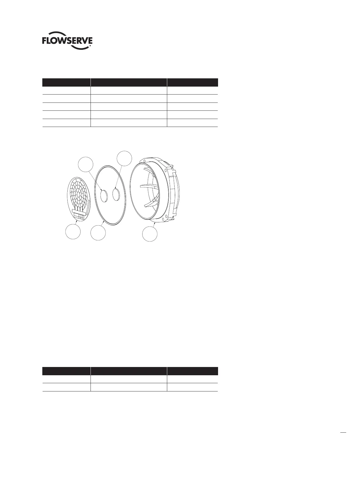
Table 6.2 - Terminal Cover Subassembly
ITEM NUMBER DESCRIPTION QTY.
8-12 TERMINAL COVER 1
8-13 O'-RING 1
8-27 LABEL, TERMINAL BLOCK 1
8-28 HOOK 1
8-29 LOOP 1
Figure 6.2 - Terminal Cover Subassembly
6.1.2 Terminal Cover Remounting
Step 1
Lightly lubricate ‘O’-ring (#8-13) and install around terminal cover spigot/pilot (#8-12). Slide terminal cover spigot/pilot
into the unit housing.
Step 2
Fit the 4 screws (#15-6) into terminal cover subassembly mounting holes and tighten to torque in section 2.
6.2 Controls Cover
Table 6.3 - Controls Cover Assembly
ITEM NUMBER DESCRIPTION QTY.
15-3 CONTROLS COVER SUBASSEMBLY 1
15-6 SOCKET HEAD CAP SCREWS 3
8-12
8-29
8-28
8-13
8-27
8-29
8-28
8-27
8-13
8-12