Limitorque QX Electronic Actuator FCD LMENIM3314-01 – 06/18
68
6.6.1 Optional Transformer Removal
c
WARNING: Hazardous Voltage! Turn off all power sources to actuator before removing control module
assembly. Power sources may include main power or control power.
a
CAUTION: Potential to cause electrostatic damage to electronic components. Before handling electronic
components, ensure that you are discharged of static electricity by briefly touching a grounded metal object.
Step 1
Remove controls cover per section 6-2.
Step 2
Remove control module per section 6-3.
Step 3
Using a M2.5 hex key, remove the four M3 screws (#2) holding the optional transformer assembly (#1) in place and
remove from back of control module. If require unplug wiring harness (#3).
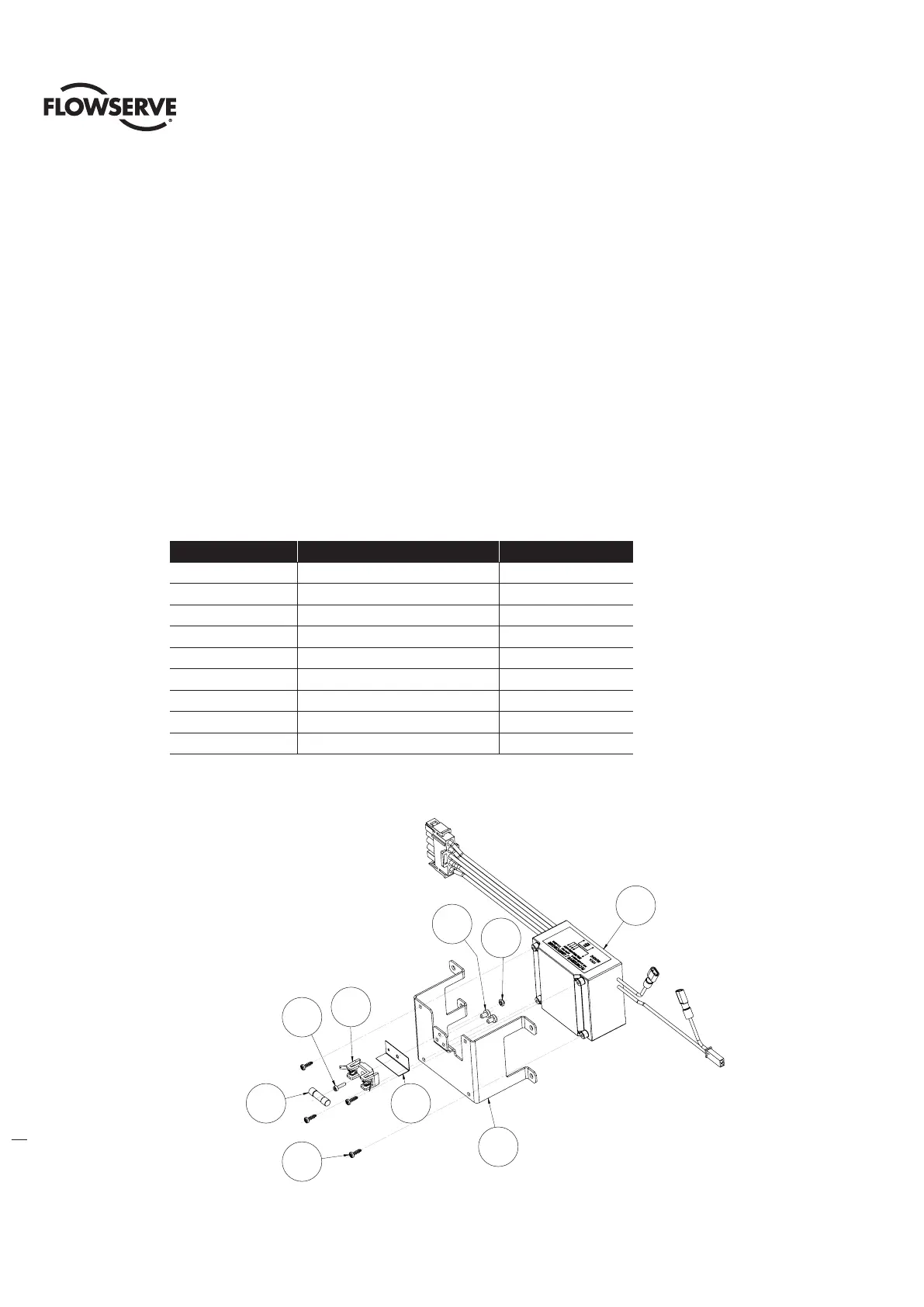
Table 6.13 - Optional Transformer Subassembly
ITEM NUMBER DESCRIPTION QTY.
1 BRACKET 1
2 OPTIONAL TRANSFORMER 1
3 SOVAL HEAD SCREW 4
4 FUSE BLOCK 1
5 SOCKET HEAD CAP SCREWS 1
6 HEX NUT 1
7 FUSE 1
8 SHIELD, FUSE BLOCK 1
9 SELF TAP SCREW 2
Figure 6.16 Optional Transformer Subassembly
2
1
6
9
8
4
7
3
5
ITEM 9
FUSE BLOCK
ANTI-ROTATION
SCREWS
1
2
6
4
5
7
3
8
9
Item 9
fuse block
anti-rotation
screws