Limitorque QX Electronic Actuator FCD LMENIM3314-01 – 06/18
72
Figure 7.4 - High Voltage QX Unit Wiring
NOTE: Check to make sure the toroid transformer has the correct ‘PRI’ voltage values for the application. See Figure
7.5 for typical labeling of toroid transformer.
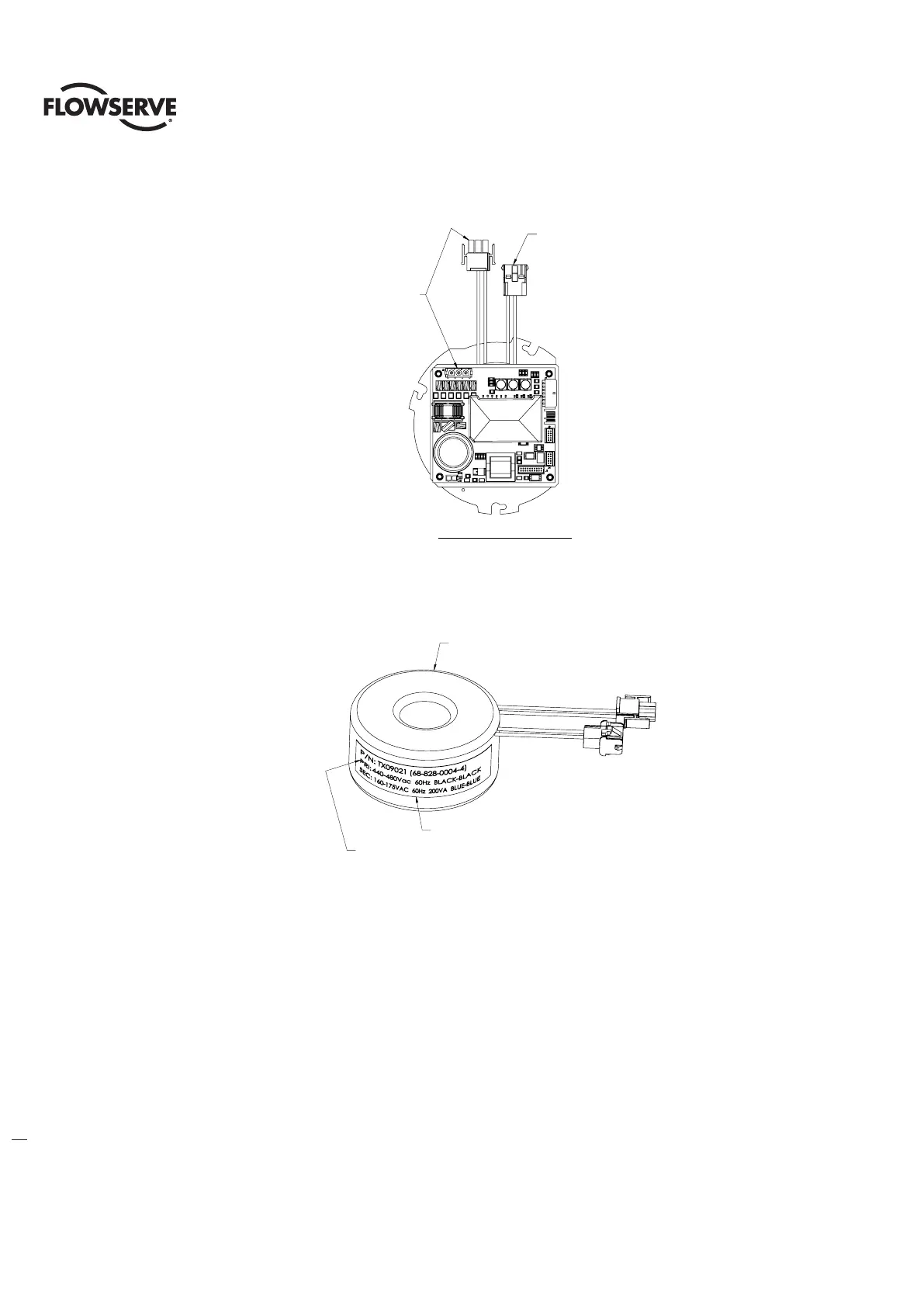
Figure 7.5 Typical Toroid Transformer Label
7.3 Optional Transformer Wiring (Cabling) Quick Reference Guide
The optional transformer uses a separate wiring harness to connect the controls supply (power in from L1, L2 and L3)
terminal block connector (J9) to the control module and optional transformer. See below for wiring configurations. All
other wiring is the same as the low or high voltage connections.
NOTE: See Figure 7.9 for wiring harness configurations per supply input voltage.
TERMINAL BLOCK 3 PIN CONNECTOR (J9)
TO TOROID TRANSFORMER BLACK-BLACK
WIRES, 3 PIN CONNECTOR
HIGH VOLTAGE MODULE ASSEMBLY
TORIOD TRANSFORMER BLUE-BLUE
WIRES, 3 PIN CONNECTOR TO
J2, 3 PIN CONNECTOR ON
MOTOR CONTROLLER BOARD
TRANSFORMER LABEL
'PRI' VOLTAGE INFO
TOROID TRANSFORMER
Toriod transformer blue-blue
Wires, 3 pin connector to
J2, 3 pin connector on
Motor controller board
Terminal block 3 pin connector (J9)
To toroid transformer black-black
Wires, 3 pin connector
Toroid transformer
‘PRI’ voltage info
Transformer label