43
Limitorque QX Electronic Actuator FCD LMENIM3314-01 – 06/18
flowserve.com
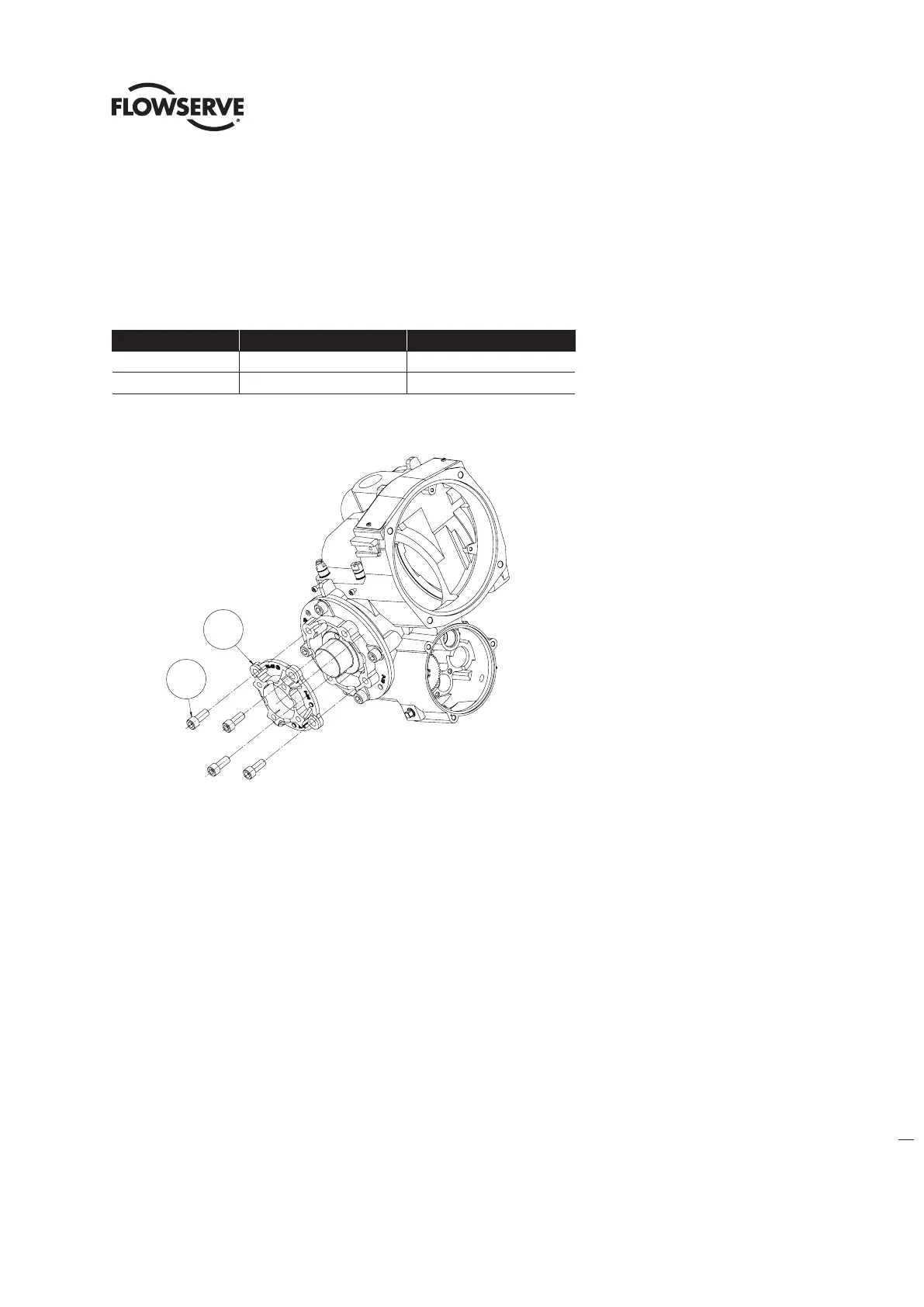
4.9 Optional Baseplate Assembly, F/FA-05 & -07 QX-1 & 2, F/FA-10 QX-3
thru 5.
4.9.1– Optional Baseplate Removal.
Table 4.20 - Optional Baseplate Removal
ITEM NUMBER DESCRIPTION QTY.
16-2 BASEPLATE 1
16-3 SOCKET HEAD CAP SCREWS 4
Figure 4.24 - F/FA-05 / 07, QX-1 & 2 or F/FA-10, QX-3 thru 5 Optional Baseplate
Step 1
QX-1 & 2, MSS FA-05 or -07 baseplate. Using a 5/6” hex key For MSS baseplate, remove the 3/8-16 screws (#4-2)
and remove baseplate (#3).
QX-1 & 2, ISO F-05 or -07 baseplate. Using a M8 hex key For ISO baseplate, remove the M10 screws (#4-2) and
remove baseplate (#3).
QX-3, 4 & 5, MSS FA-10 baseplate. Using a ½” hex key For MSS baseplate, remove the 5/8-11 screws (#4-2) and
remove baseplate (#3).
QX-3, 4 & 5, ISO F-10 baseplate. Using a M14 hex key For ISO baseplate, remove the M16 screws (#4-2) and remove
baseplate (#3).
4.9.2 – Optional Baseplate Remounting.
NOTE: For small baseplate the torque nut must be mounted to drive sleeve before mounting baseplate.
See section 4-11-1.
Place small baseplate on large baseplate aligning pilot. Place screws in baseplate holes and tighten.
16-2
16-3
16-3
16-2