Limitorque QX Electronic Actuator FCD LMENIM3314-01 – 06/18
18
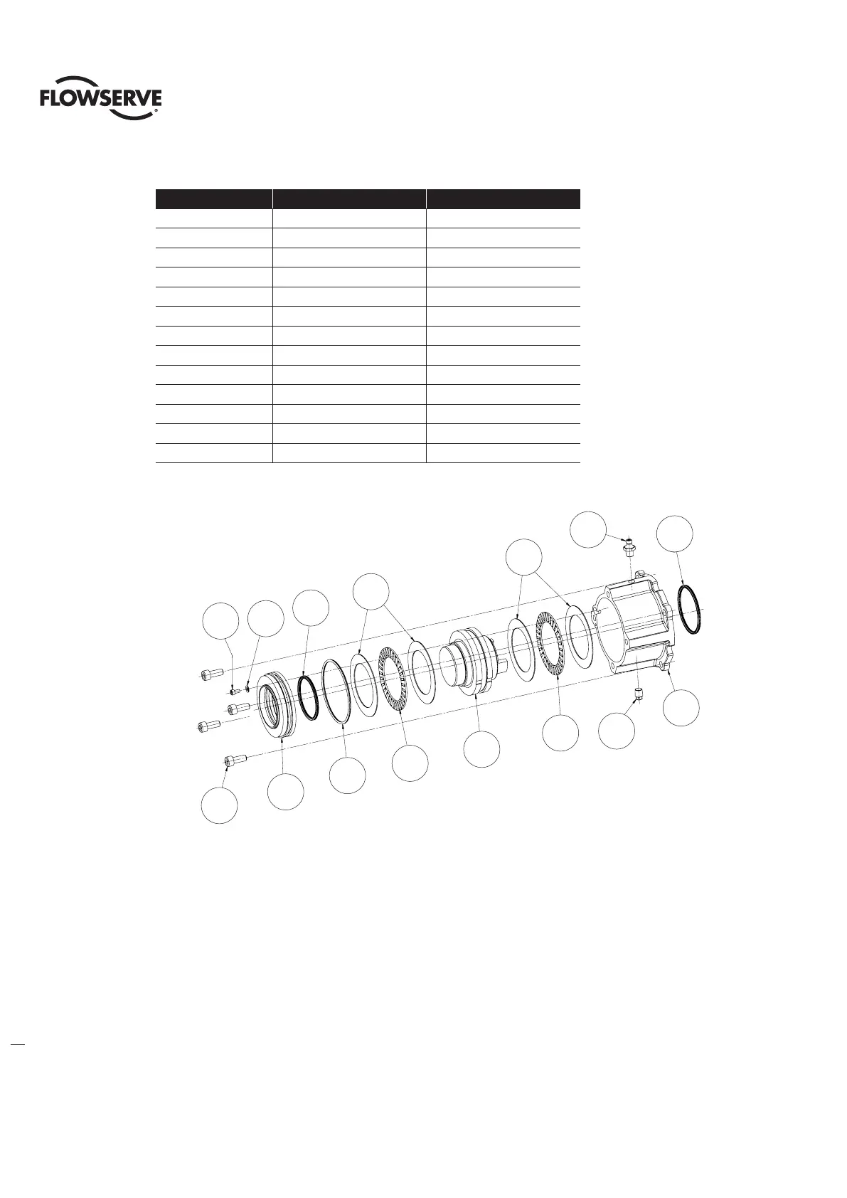
Table 3.3 - Optional Thrust Base Subassembly
ITEM NUMBER DESCRIPTION QTY.
10-1 HOUSING, THRUST BASE 1
10-2 PILOT, THRUST BASE 1
10-3 THRUST NUT 1
10-6 SOCKET HEAD CAP SCREWS 1
10-7 FLAT WASHER 1
10-8 RELIEF FITTING 1
10-10 SOCKET HEAD CAP SCREWS 4
10-11 GREASE FITTING 1
10-12 NEEDLE BEARING 2
10-13 THRUST RACE 2
10-14 QUAD RING 1
10-15 O'-RING 1
10-16 QUAD RING 1
Figure 3.4 - Optional Thrust Base Subassembly
3.2.3 Thrust base remounting
Step 1
Place QX torque nut (#16-10) into unit drive sleeve (#1-11) aligning nut lugs to drive sleeve slots.
Step 2
Lightly lubricate ‘O’-rings (#16-12) and (#16-13) and insert into bushing (#16-11) that is pressed into adapter plate
(#16-14). Slide adapter plate and bushing over end of torque nut and aligning to unit baseplate. Insert screws (#16-15)
into adapter plate holes and tighten.
Step 3
Align thrust base subassembly nut lugs (#10-3) with QX torque nut (#16-10) slots and slide thrust base on to QX
unit baseplate aligning pilots. Note; For ISO thrust base pilot spacer (#16-16) must be used to align thrust base to QX
baseplate. Insert screws (#10-10) into thrust base holes and tighten
10-14
10-11
10-1
10-8
10-13
10-13
10-12
10-12
10-3
10-15
10-16
10-710-6
10-10
10-2
10-6
10-7
10-16
10-10
10-2
10-15
10-12
10-13
10-11
10-14
10-13
10-1
10-8
10-3
10-12