Limitorque QX Electronic Actuator FCD LMENIM3314-01 – 06/18
40
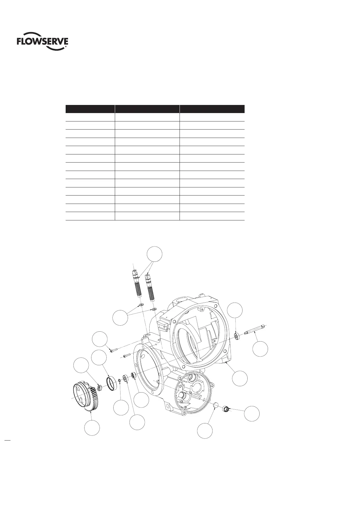
4.8 Drive Sleeve, Stops and Encoder Shaft Assemblies
NOTE: Sections 4.2 – 4.8 require the actuator to be removed from the mounting plate and the oil drained
Table 4.18 - Drive Sleeve, Stops, and Encoder Shaft Assembly
ITEM NUMBER DESCRIPTION QTY.
1-1 HOUSHING 1
1-2 BUSHING 1
1-3 OIL SEAL 1
1-5 BALL BEARING (SEALED) 2
1-6 SHAFT, ENCODER 1
1-7 RETAINING RING 1
1-8 DISC 1
1-9 NEEDLE BEARING 1
1-10 INSERT 1
1-11 DRIVE SLEEVE 1
1-12 STOPS 2
1-13 O-RING 2
1-14 SOCKET HEAD CAP SCREW 2
Figure 4.21 - Drive Sleeve, Stops, and Encoder Shaft Assembly
1-2
1-5
1-3
1-7
1-10
1-11
1-14
1-12
1-13
1-5
1-6
1-1
1-8
1-9
90
UNIT STOPS SHOWN
1-5
1-6
1-1
1-9
1-8
1-3
1-5
1-7
1-11
1-12
1-13
1-14
1-2
1-10
90° unit stops shown