67
Limitorque QX Electronic Actuator FCD LMENIM3314-01 – 06/18
flowserve.com
Table 6.11 - Screw Part Numbers
BOARD DESCRIPTION SCREW PART NUMBER DESCRIPTION QTY.
MAIN WITH
NO OPTION BOARDS
64-818-0001-35 M4X8 4
MAIN WITH
1 OPTION BOARD
64-818-0001-32 M4X25 4
MAIN WITH
2 OPTION BOARDS
64-818-0001-36 M4X40 4
MAIN WITH
3 OPTION BOARDS
64-818-0004-3 M4X55 4
MAIN WITH
4 OPTION BOARDS
64-818-0005-3 M4X70 4
a
CAUTION: Potential to pinch cables. When remounting ACP cover, take special care no to pinch ribbon cables.
Dress the cables being careful to position wires so that they pass perpendicularly over the housing flange.
NOTE: The face of the ACP may be installed in any one of four 90° incremental positions. When changing ACP
position, avoid over-twisting the ribbon cable(s).
Rotate the ACP until the display orientation of the front face is correct for normal viewing, and then slide the ACP
assembly into the actuator housing.
6.5.2 Removal
For removal, follow installation instructions in reverse.
6.6 Optional Transformer
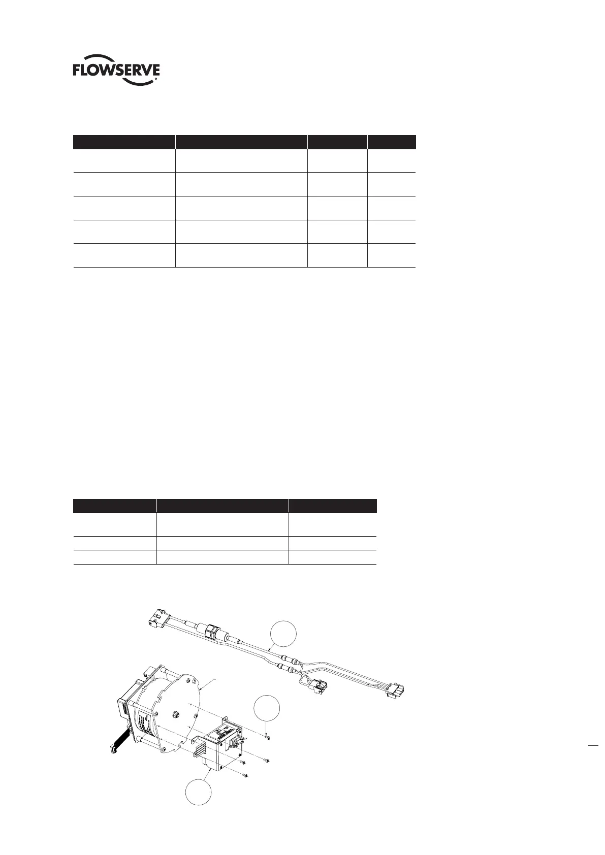
Table 6.12 - Optional Transformer Assembly
ITEM NUMBER DESCRIPTION QTY.
1
OPTIONAL TRANSFORMER
SUBASSEMBLY
1
2 SOCKET HEAD CAP SCREWS 4
3 WIRING HARNESS 1
Figure 6.15 - Optional Transformer Assembly
1
2
CONTROL MODULE
CHASSIS PLATE
3
1
2
3
Control module
chassis plate