Limitorque QX Electronic Actuator FCD LMENIM3314-01 – 06/18
56
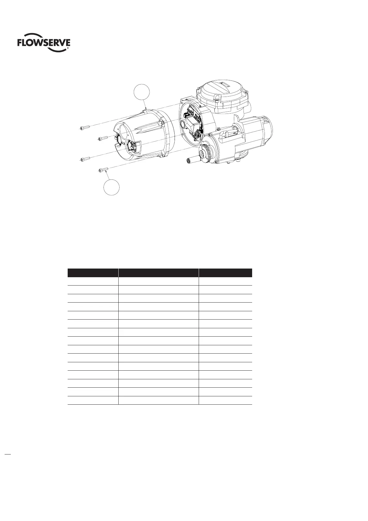
Figure 6.3 - Controls Cover Assembly
6.2.1 Controls Cover Removal
Step 1
Using a M6 hex key, remove the four M8 screws (#15-6) that mount the Controls cover subassembly and remove
cover (#15-3).
NOTE: When removing cover take care not to pull on cables that connect to the controls cover main board.
Table 6.4 - Controls Cover Subassembly
ITEM NUMBER DESCRIPTION QTY.
1-49 SHIELD, MAIN BOARD 1
7-2 O'-RING 1
7-3 BLACK KNOB 1
7-4 RED KNOB 1
7-6 SELF TAPPING SCREW 2
7-7 BLACK KNOB CAP 1
7-12 TORSION SPRING 1
7-14 RED KNOB CAP 1
7-17 CONTROLS COVER 1
7-18 WINDOW 1
7-19 O'-RING RETAINER 1
7-20 RETAINING RING 1
7-21 O'-RING 1
7-44 PAN HEAD MACHINE SCREW 4
8-24 PC BOARD, MAIN 1
15-3
15-6
15-3
15-6