27
Limitorque QX Electronic Actuator FCD LMENIM3314-01 – 06/18
flowserve.com
4.2.2 Handwheel Cover Assembly Remounting
Step 1
Lightly lubricate ‘O’-ring (#15-2) and install around handwheel cover subassembly pilot (#10). Slide ball bearing
(#9-13) back on end of clutch assembly if bearing was removed. Slide handwheel cover assembly pilot (#10) into the
unit housing assuring the ball bearing aligns in handwheel shaft bore and dowel pin (13-1) aligns with the pin hole in
cover.
NOTE: for QX-3,4 and 5 Handwheel assembly must also align with Ball bearing (#9-3) and the idle shaft assembly, see
Figure 4.10 for view of idle shaft assembly location.
Step 2
Fit the 3 screws (#13-3) into handwheel cover mounting holes and tighten.
Check to make sure handwheel rotates freely.
4.3 Motor Cartridge Subassembly, QX-1 thru 5.
NOTE: Sections 4.2 – 4.8 require the actuator to be removed from the mounting plate and the oil drained.
4.3.1 Motor Cartridge Subassembly Removal, QX-1 thru 5.
Table 4.7 Motor Cartridge Assembly Removal
ITEM NUMBER DESCRIPTION QTY.
5 MOTOR CARTRIDGE 1
9-1 TAB, BRACKET 1
9-2 SOCKET HEAD CAP SCREW 1
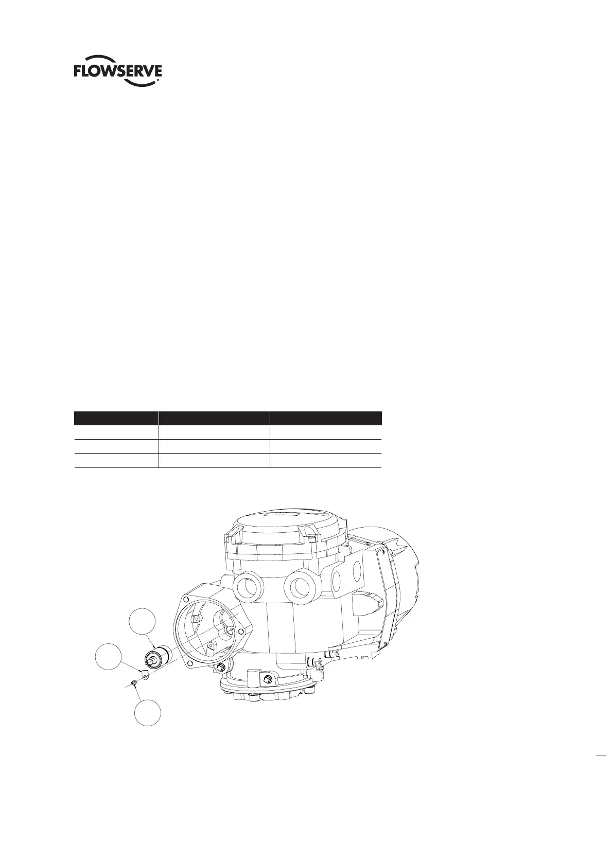
Figure 4.8 - Motor Cartridge Assembly Removal
Step 1
Using a M3 hex key, remove the M4 screw (#9-2) and bracket (#9-1). Grab end of motor cartridge shaft and pull out
cartridge subassembly.
9-2
9-1
5
9-1
5
9-2