Limitorque QX Electronic Actuator FCD LMENIM3314-01 – 06/18
22
4.1.1 Motor subassembly Removal. QX-1 thru 5.
Step 1
c WARNING: Hazardous Voltage! Turn off all power sources to actuator before removing motor assembly. Power
sources may include main power or control power.
Using a M6 hex key, remove the three M8 screws (#15-6) that mount the motor cover and remove cover (#15-2) and
‘O’-ring (#15-1) from unit assembly.
NOTE: The controls cover must also be removed to disconnect the motor cable from the motor controller if the motor
is to be completely removed. See Section 6.2 for controls cover removal, Section 7.1 for motor connector placement.
Step 2
a
CAUTION: The rotor is not connected to the motor housing; when removing the motor, ensure the rotor is
carefully removed and not dropped from the motor housing.
Using a M3 hex key, remove the five M4 screws (#13-4) that mount the motor assembly. Remove the motor assembly
(#11) from unit by sliding motor out of the unit and if needed disconnect motor connector from motor control board
and slide wiring out of unit.
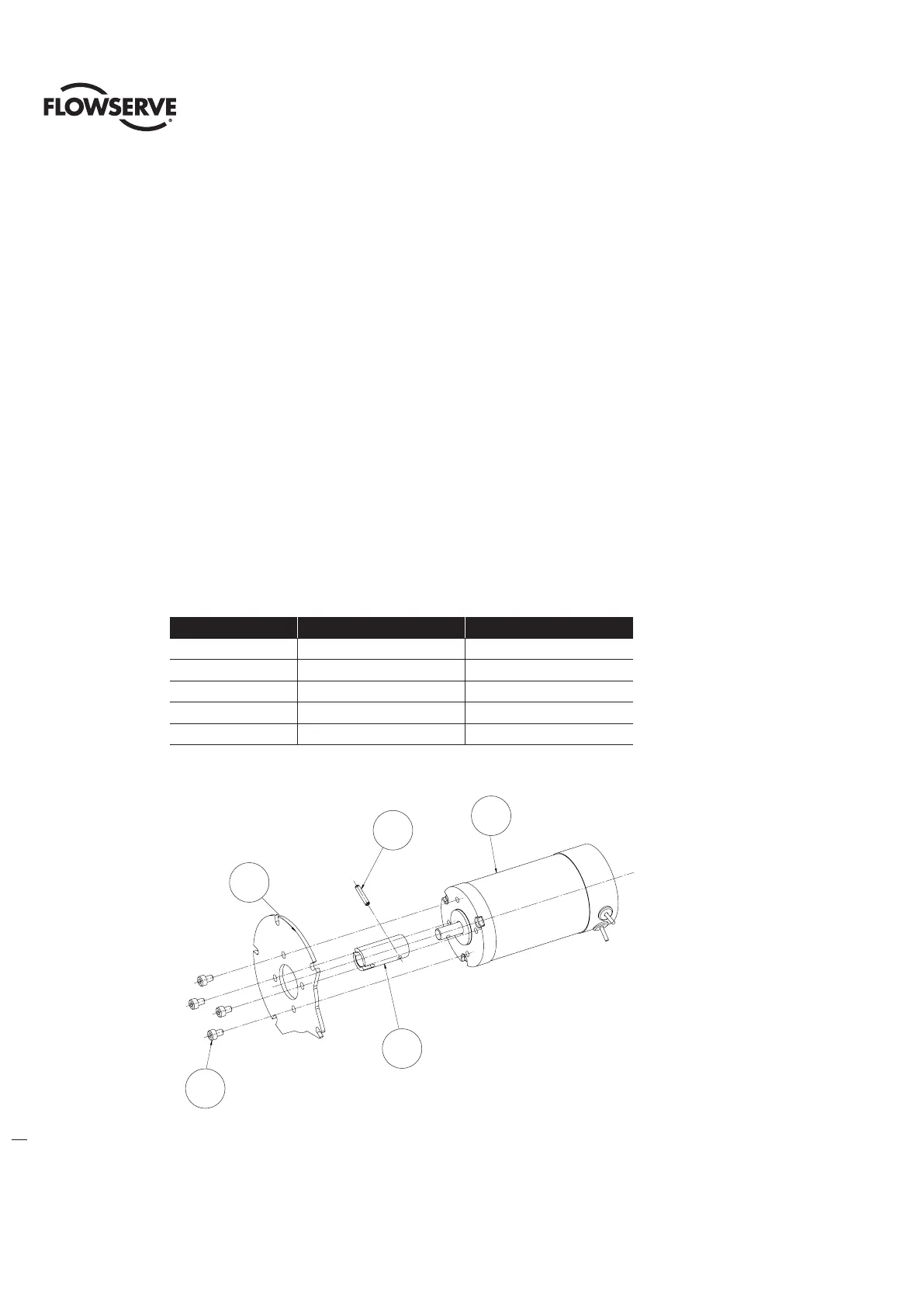
Table 4.2 Motor Subassembly, Item 11
ITEM NUMBER DESCRIPTION QTY.
11-1 MOTOR 1
11-2 COUPLING 1
11-3 SPIRAL PIN 1
11-4 PLATE, MOTOR MOUNTING 1
11-5 SOCKET HEAD CAP SCREWS 1
Figure 4.2 - Motor Subassembly, Item11
11-1
11-2
11-4
11-5
11-3
11-1
11-3
11-4
11-5
11-2