Limitorque QX Electronic Actuator FCD LMENIM3314-01 – 06/18
54
6
Electronic Assemblies
6.1 Terminal Cover
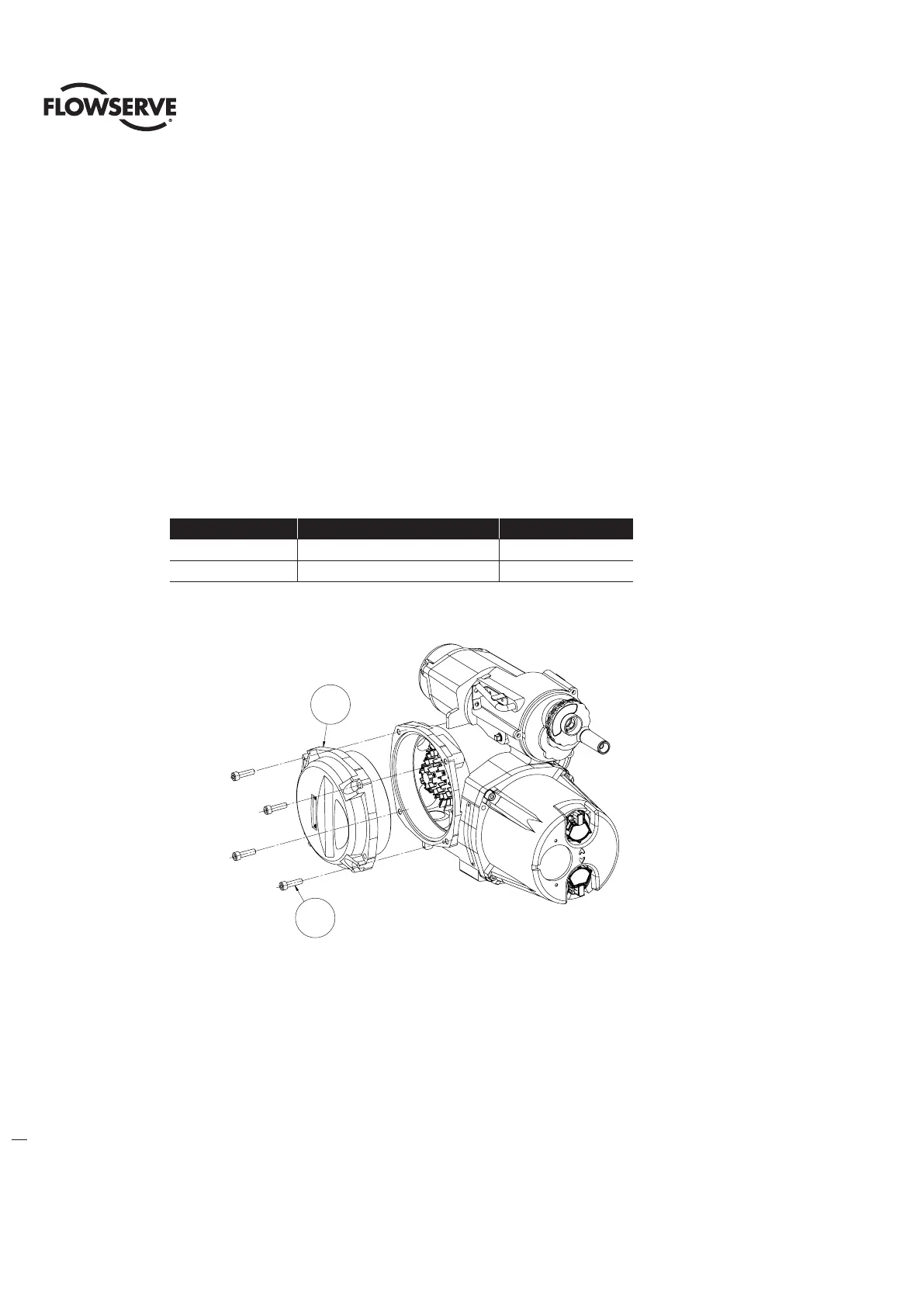
Table 6.1 - Terminal Cover Assembly
ITEM NUMBER DESCRIPTION QTY.
15-5 TERMINAL COVER SUBASSEMBLY 1
15-6 SOCKET HEAD CAP SCREWS 3
Figure 6.1 - Terminal Cover Assembly
6.1.1 Terminal Cover Removal
c
WARNING: Hazardous Voltage! Turn off all power sources to actuator before removing control module
assembly. Power sources may include main power or control power.
a
CAUTION: Potential to cause electrostatic damage to electronic components. Before handling electronic
components, ensure that you are discharged of static electricity by briefly touching a grounded metal object.
Step 1
Using a M6 hex key, remove the four M8 screws (#15-6) that mount the Terminal cover subassembly and remove
cover (#15-5).
15-5
15-6
15-5
15-6