65
Limitorque QX Electronic Actuator FCD LMENIM3314-01 – 06/18
flowserve.com
Installation with option boards:
1. Move JP1 jumper to the ‘NORM’ position
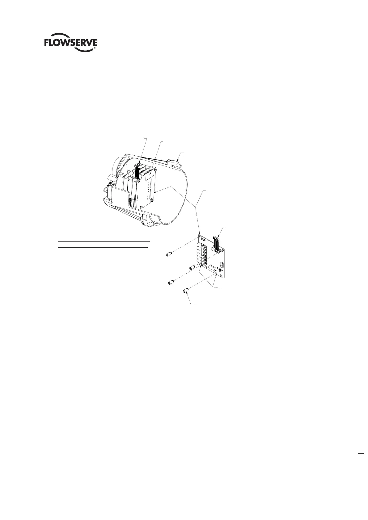
2. Insert PCB standoffs on populated side of board in holes marked ‘A’ as shown in Figure 6.13.
3. Mount board at end of board stack, plugging ribbon cable into the J2 receptacle on main board as shown
Figure 6.13 - Quik Power With Option Boards
Work on electronics if Quik Board is installed
1. Cycle through CHANGE SETTINGS menu until you reach CHANGE BACKUP POWER.
2. Select YES
3. Select BACKUP POWER DISABLED – OK?
4. Select YES
5. Exit CHANGE SETTINGS MENU
6. Turn power off to actuator, LCD and LEDS should still operate once power is removed. This is due to the quik board
still supplying power. Wait for unit to shut off.
7. Carefully remove electronics and Quik Board.
8. Locate JP1 (jumper) on JP1 of Quik Board and move to FAST DISCHARGE PINS.
PLACE STANDOFFS IN HOLES
MARKED 'A'
RIBBON CABLE INCLUDED
W/ BOARD COMPONENTS
4X STANDOFF
(MOUNTED THIS SIDE
AS SHOWN)
QUIK POWER BOARD
MUST BE MOUNTED AT END
OF BOARD STACK
CONTROLS COVER
ASSEMBLY
CONNECT RIBBON CABLE
TO J2 ON MAIN BOARD
WHEN USED WITH OPTION BOARDS,
QUIK POWER BOARD TO BE MOUNTED WITH
COMPONENTS FACING BOARD STACK
AS SHOWN
VIEW - CONTROLS COVER ASSEMBLY
QUIK POWER WITH OPTION BOARDS
VIEW - CONTROLS COVER ASSEMBLY
QUIK POWER WITH OPTION BOARDS
Connect ribbon cable
To j2 on main board
Quik power board
Must be mounted at end
Of board stack
Controls cover
Assembly
When used with option boards,
Quik power board to be mounted with
Components facing board stack
As shown
Ribbon cable included
W/ board components
4X standoff
(Mounted this side
As shown)
Place standoffs in holes
marked ‘A’