Limitorque QX Electronic Actuator FCD LMENIM3314-01 – 06/18
50
5.2 Multi Turn Encoder. QXM-1 thru 5, all RPMs
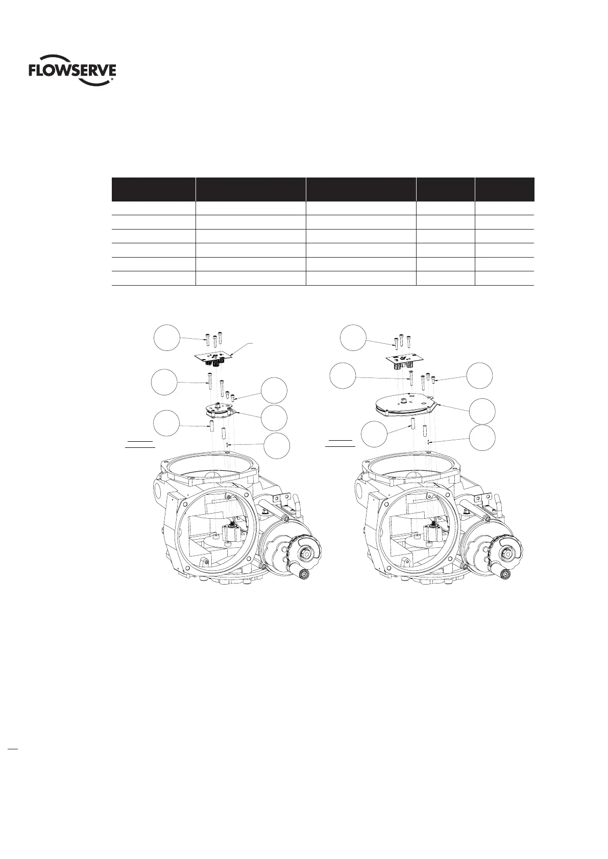
Table - 5.3 Multi-Turn Encoder Assembly
ITEM NUMBER
DESCRIPTION
(6.5 TURN)
DESCRIPTION
(20 TURN)
QTY.
(QX-1 &2)
QTY.
(QX-3 THRU 5)
17-1 DOWEL PIN DOWEL PIN 1 1
17-2 6.5 TURN SPUR GEAR ASSY SPUR GEAR ASSY 1 1
17-3 SOC HEAD CAP SCREW SOC HEAD CAP SCREW 2 2
17-4 SPACER SPACER 2 NA
17-5 SOCKET HEAD CAP SCREWS SOCKET HEAD CAP SCREWS 2 2
17-6 SOCKET HEAD CAP SCREWS SOCKET HEAD CAP SCREWS 3 3
Figure 5.4 - Multi-turn Encoder Assembly
5.2.1 Multi Turn Encoder Removal
Step 1
NOTE: The terminal block and power controls must be removed before removing the encoder. See section 6.4 for
terminal block and controls removal.
Disconnect the encoder ribbon cable connector from the Motor controller board, See section 6 for connector
placement. Using M3 Hex key remove the three screws (#17-6) that mount the encoder. Gently pull the encoder up and
out of the housing thru the terminal block bore.
Step 2
Using M3 Hex key (QX-1 & 2) or M2.5 Hex key (QX-3 thru 5) remove the two screws (#17-5) that mount the encoder
spur gear subassembly to the two housing pads.
17-2
17-4
17-5
17-3
ITEM 14-1
SEE SHT 14
17-6
17-1
6.5 TURN
ASSEMBLY
20 TURN
ASSEMBLY
17-6
17-5
17-4
17-3
17-2
17-1
APPLY LOCTITE 222
ON THESE TWO
FLAT HEAD SCREWS
17-1
17-2
17-3
17-4
17-5
17-6
Apply loctite 222
on these two
at head screws
17-6
17-5
17-4
17-1
17-2
17-3
Item 14-1
See sht 14