Limitorque QX Electronic Actuator FCD LMENIM3314-01 – 06/18
64
Connect to the control cover using four (4) M4x40pan head screws. Ensure that primary board jumper (board “A”) is
in the “A” position and redundant board jumper (board “B”) is in the “B” position. Connect the J7 6-pin cable from the
terminal block to socket J8 on the “A” board and J3 4-pin connector for the redundant board “B”.
STEP 8 – PROFIBUS-PA NETWORK BOARD CONNECTION
Connect to the control cover using four (4) M4x25 pan head screws if one Profibus-PA board is installed. Ensure that
both jumpers are in the “A” position. Connect the J7 6-pin cable from the terminal block to socket J8.
STEP 9 – FOUNDATION FIELDBUS NETWORK BOARD CONNECTION
Connect to the control cover using four (4) M4x25 pan head screws if one FOUNDATION Fieldbus board is installed.
Ensure that both jumpers are in the “A” position. Connect the J7 6-pin cable from the terminal block to socket J8.
STEP 10 - DEVICENET NETWORK BOARD CONNECTION
Connect to the control cover using four (4) M4x25 pan head screws if one DeviceNet board is installed. Ensure that
both jumpers are in the “A” position. Connect the 6-pin cable from the terminal block to socket J8. Set aside yellow
ground wire to be fastened to top of option board stack per Figure 6.14. Above the shield, the wire must make contact
with the screw.
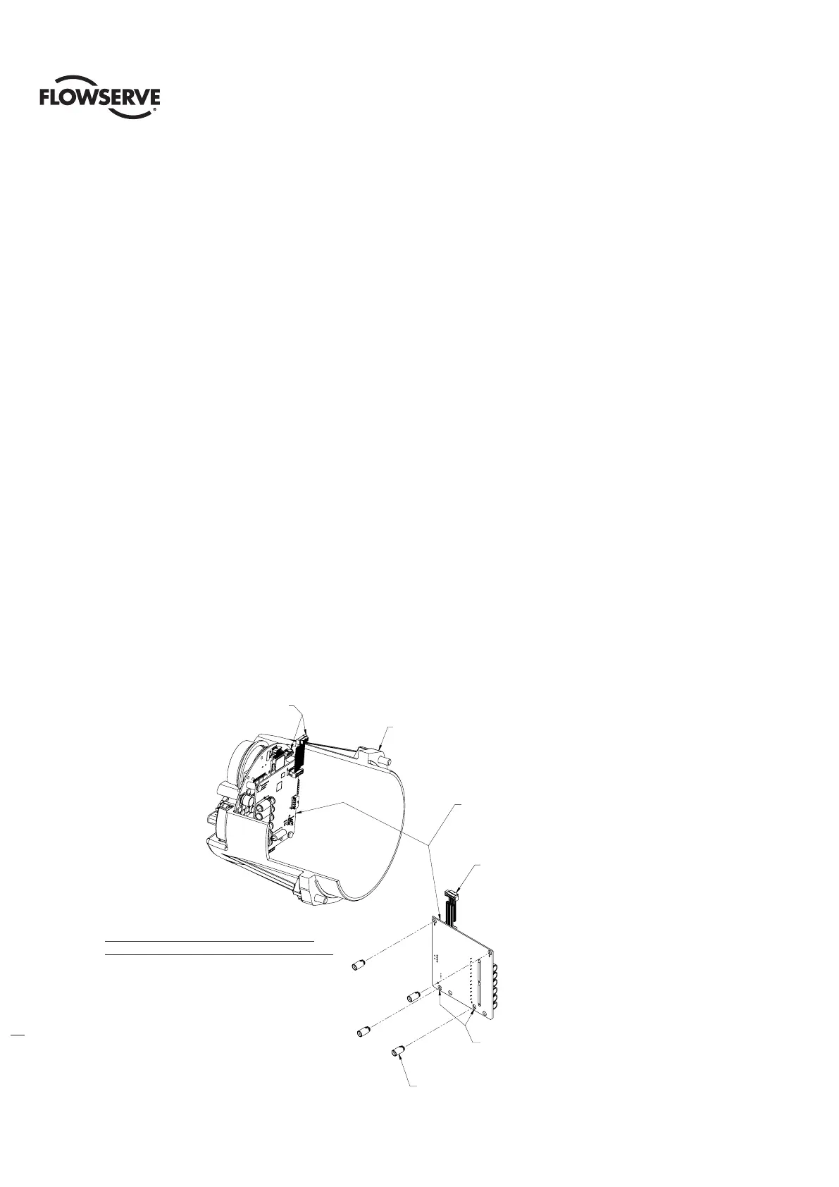
STEP 11 – QX Quik (auxiliary) power board
a
CAUTION: Use proper tools and only apply light pressure when installing standoffs to avoid damage to circuit
board.
Installation without option boards:
1. Move JP1 jumper to the ‘NORM’ position
2. Insert PCB standoffs on unpopulated side of board in holes marked ‘B’ as shown in Figure 6.13
3. Plug ribbon cable into the J2 receptacle on main board as shown
Figure 6.12 Quik Power Without Option Boards
PLACE STANDOFFS IN HOLES
MARKED 'B'
4X STANDOFF
(MOUNTED THIS SIDE
AS SHOWN)
RIBBON CABLE INCLUDED
W/ BOARD COMPONENTS
CONTROLS COVER
ASSEMBLY
CONNECT RIBBON CABLE
TO J2 ON MAIN BOARD
VIEW - CONTROLS COVER ASSEMBLY
QUIK POWER WITHOUT OPTION BOARDS
WHEN USED WITHOUT OPTION BOARDS,
QUIK POWER BOARD TO BE MOUNTED WITH
COMPONENTS FACING OUTWARD FROM
MAIN BOARD AS SHOWN
Connect ribbon cable
to J2 on main board
Controls cover
assembly
When used without option boards,
quik power board to be mounted with
components facing outward from
main board as shown
Ribbon cable included
w/ board components
Place standoffs in holes
marked ‘B’
4X standoff
(Mounted this side
As shown)
VIEW - CONTROLS COVER ASSEMBLY
QUIK POWER WITHOUT OPTION BOARDS