Limitorque QX Electronic Actuator FCD LMENIM3314-01 – 06/18
24
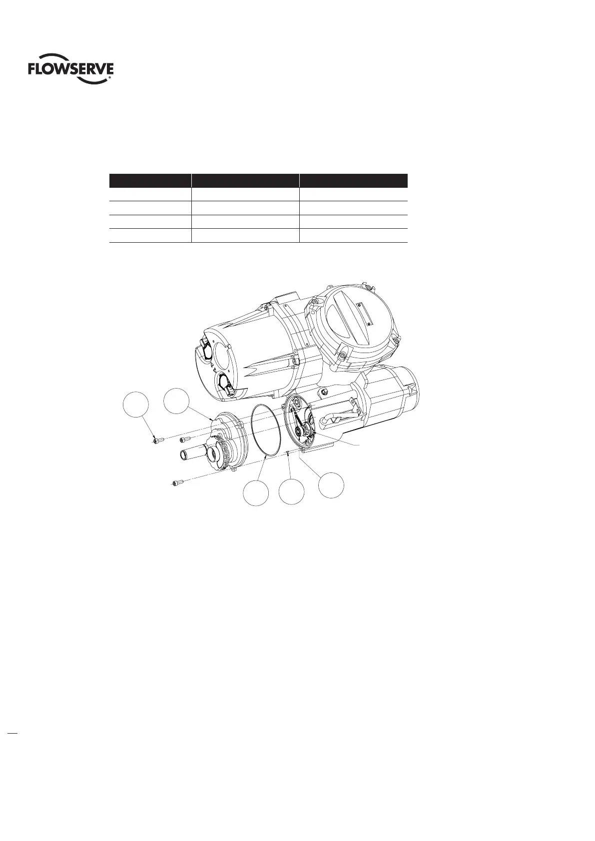
4.2 Handwheel cover subassembly, QX-1 thru 5.
NOTE: Sections 4.2 – 4.8 require the actuator to be removed from the mounting plate and the oil drained.
Table 4.3 - Handwheel Cover Assembly
ITEM NUMBER DESCRIPTION QTY.
10 HANDWHEEL COVER ASSY 1
13-1 DOWEL PIN 1
13-2 'O'-RING 1
13-3 SOCKET HEAD CAP SCREW 3
Figure 4.4 - Handwheel Cover Assembly
c WARNING: Do not manually operate the actuator with devices other than the installed handwheel and declutch
lever. Using force beyond the ratings of the actuator and/or additive forces such as cheater bars, wheel
wrenches, pipe wrenches, or other devices on the actuator handwheel or declutch lever may cause serious
personal injury and/or damage to the actuator and valve.
4.2.1 – Handwheel cover subassembly Removal, QX-1 thru 5
Step 1
c WARNING: Potential to operate while dangerous mechanical parts are exposed during subassembly removal.
To prevent injury, turn off all power sources to actuator before removing top-mounted handwheel assembly.
Power sources may include main power or control power.
Using a M5 hex key, remove the three M6 screws (#13-3) that mount the handwheel cover and remove the handwheel
cover assembly (#10) and ‘O’-ring (#13-2) from unit assembly. Dowel pin (#13-1) is pressed into the unit housing.
Note: QX-1 thru 5 Ball bearing (#9-13) may also come out with the handwheel assembly, QX-3,4 and 5 Ball bearing
(#9-3) may also come out with the handwheel assembly.
13-113-2
10
13-3
9-13
CLUTCH SHAFT ASSEMBLY (#6)
9-13
13-1
13-2
13-3
10
Clutch shaft assembly (#6)