Limitorque QX Electronic Actuator FCD LMENIM3314-01 – 06/18
46
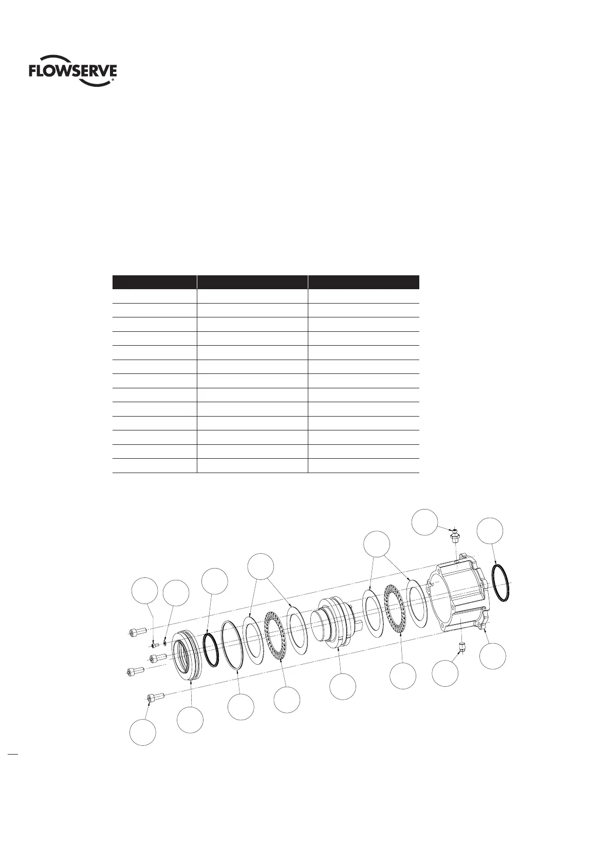
4.11.1 Optional Thrust Base Assembly Removal.
Step 1
Remove the four (4) screws (# ) and remove the thrust base subassembly (#16-17) by sliding the base down. If base
is ISO remove the spacer (pilot) (#16-16).
Step 2
Remove the four (4) screws (# 16-15) and remove the adapter plate (#16-14) and torque nut (#16-10). Item (#16-11)
bushing is pressed into adapter plate and cannot be removed. The torque nut is held in place by the unit drive sleeve
and the bushing (#16-11).
Table 4.24 Optional Thrust Base Subassembly
ITEM NUMBER DESCRIPTION QTY.
10-1 HOUSING, THRUST BASE 1
10-2 PILOT, THRUST BASE 1
10-3 THRUST NUT 1
10-6 SOCKET HEAD CAP SCREWS 1
10-7 FLAT WASHER 1
10-8 RELIEF FITTING 1
10-10 SOCKET HEAD CAP SCREWS 4
10-11 GREASE FITTING 1
10-12 NEEDLE BEARING 2
10-13 THRUST RACE 2
10-14 QUAD RING 1
10-15 O'-RING 1
10-16 QUAD RING 1
Figure 4.28 - Optional Thrust Base Subassembly
10-14
10-11
10-1
10-8
10-13
10-13
10-12
10-12
10-3
10-15
10-16
10-710-6
10-10
10-2
10-6
10-7
10-1
10-8
10-3
10-2
10-16
10-13
10-13
10-14
10-11
10-12
10-12
10-15
10-10