51
Limitorque QX Electronic Actuator FCD LMENIM3314-01 – 06/18
flowserve.com
NOTE: For the 20 turn encoder assembly the slots in the big gear must be aligned with the top and bottom plate to
access screws (#17-5). To do this the encoder shaft and/or drive sleeve must be rotated to the correct position aligning
slots. See Figure 5.4 for orientation view.
Using M3 Hex key remove the two screws (#17-3) that mount the encoder spur gear subassembly to the housing
encoder pad. Gently pull the spur gear subassembly up and over encoder shaft and pinion and out the controls area
bore in housing.
QX-1 and 2 remove the two spacers (#17-4) (not used in QX-3 thru 5). The dowel pin (#17-1) is press into the
housing.
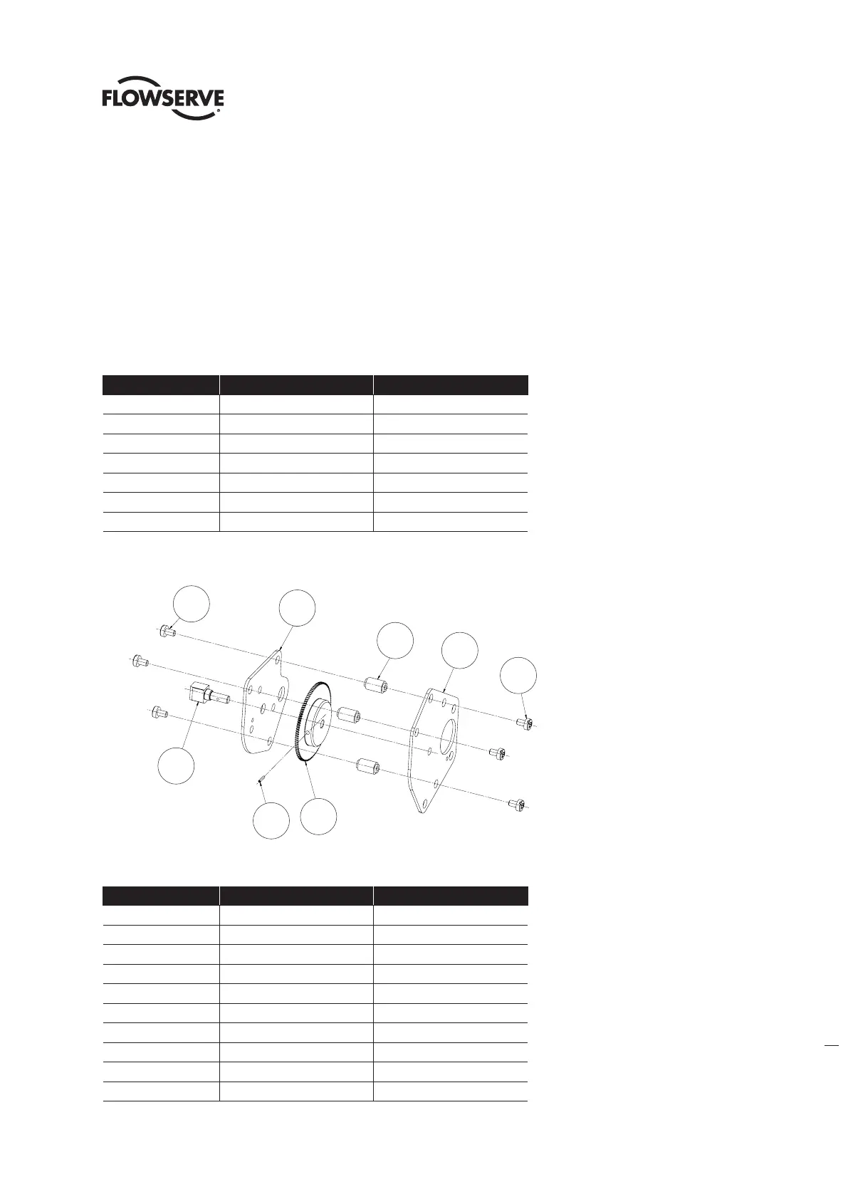
Table 5.4 - 6.5-Turn Spur Gear Subassembly I(tem 17-2)
ITEM NUMBER DESCRIPTION QTY.
1 TOP PLATE 1
2 SHAFT, ENCODER 1
3 GEAR 1
4 ROLL PIN 1
5 BOTTOM PLATE 1
6 STANDOFF 3
7 COMBO HEAD SCREW 6
Figure 5.5 - 6.5-Turn Spur Gear Subassembly (Item 17-2)
Table 5.5 - 20-Turn Spur Gear Subassembly (Item 17-2.)
Pc NUMBER DESCRIPTION QTY.
1 TOP PLATE 1
2 SHAFT, ENCODER 1
3 HUB, GEAR 1
4 ROLL PIN 1
5 DOWEL PIN 1
6 GEAR 1
7 FLAT HEAD SCREW 4
8 STANDOFF 3
9 BOTTOM PLATE 1
10 COMBO HEAD SCREW 6
1
2
3
4
6
7
7
5
1
7
6
5
7
2
4
3