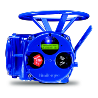
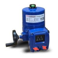
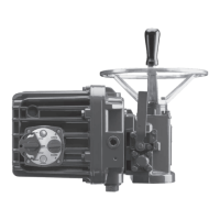
Limitorque QX Electronic Actuator FCD LMENIM3314-01 – 06/18
4
8 Spares and Replacement Parts 75
8.1 Guidelines for Recommended Spare Parts 75
8.1.1 Wear Components 75
8.1.2 Bearings, O-rings, and Seals 75
8.1.3 Critical Components 75
8.2 Recommended Spare Parts for QX Actuators 76
8.2.1 Commissioning and Startup 76
8.2.2 Short-Term Duty 76
8.2.3 Long-Term Duty 76
8.2.4 Severe Duty 76
8.3 Other Concerns 77
9 Regulatory Information 78
9.1 Declaration of Conformity 78
9.2 Specific Conditions for Use — Atex/Cenelec/IECEx Applications 80
9.3 Statement of Compliance with Applicable European Directives 80
Figures
Figure 2.1 Typical QX Actuator 7
Figure 2.2 QX Nameplate 11
Figure 2.3 QX Nameplate 11
Figure 2.4 QX Oil fill /Plug Locations (QX-1 thru 5) 13
Figure 3.1 Torque Nut, F/FA-10, QX-1 & 2 and F/FA-12 and -14, QX-1 thru 5 15
Figure 3.2 Torque Nut, F/FA-05 and -07, QX-1& 2 and F/FA-10, QX-1 thru 5 16
Figure 3.3 Optional Thrust Base Assembly 17
Figure 3.4 Optional Thrust Base Subassembly 18
Figure 4.1 Motor Cover and Motor Subassembly Removal 21
Figure 4.2 Motor Subassembly, Item11 22
Figure 4.3 Motor Bracket Orientation View 23
Figure 4.4 Handwheel Cover Assembly 24
Figure 4.5 Handwheel Cover Subassembly, Item 10. QX-1 & 2 25
Figure 4.6 Handwheel Cover Subassembly, Item 10. QX-3 thru 5 26
Figure 4.7 Handwheel Subassembly, Item 10-4. QX-1 & 2 shown 26
Figure 4.8 Motor Cartridge Assembly Removal 27
Figure 4.9 Motor Cartridge Subassembly, Item 5 28
Figure 4.10 Gearing and clutching, QX-1 & 2 29
Figure 4.11 Gearing and clutching, QX-3 thru 5 30
Figure 4.12 Clutch Shaft Subassembly, Item 6. QX-1 & 2 32
Figure 4.13 Clutch Shaft Subassembly, Item 6. QX-3 thru 5 32
Figure 4.14 Clutch Shaft Subassembly, Item 7 33
Figure 4.15 Clutch Fork Shaft Remounting 34
Figure 4.16 Declutch Spring Assembly View. QX-1 & 2 shown 34
Figure 4.17 Pipe Plug 35
Figure 4.18 Baseplate, F/FA-10 QX-1 & 2, F/FA-12 & 14, QX-3 thru 5 36
Figure 4.19 F/FA-10 QX-1 & 2, F/FA-12 & 14, QX-3 thru 5 Baseplate Subassembly, Item 3 36
Figure 4.20 Worm Shaft 38
Figure 4.21 Drive Sleeve, Stops, and Encoder Shaft Assembly 40
Figure 4.22 Multi-turn Encoder Shaft Subassembly (Item 1-6) 41
Figure 4.23 Stop Groove View 42
Figure 4.24 F/FA-05 / 07, QX-1 & 2 or F/FA-10, QX-3 thru 5 Optional Baseplate 43
Figure 4.25 Torque nut, F/FA-10, QX-1 & 2 and F/FA-12 and -14, QX-1 thru 5 44
Figure 4.26 Torque nut, F/FA-05 and -07, QX-1 & 2 and F/FA-10, QX-1 thru 5 44
Figure 4.27 Optional Thrust Base Assembly QXM Only 45

 Loading...

