5.2 Function Code Tables
[ 9 ] J codes: Application Functions 1 (Application function 1)
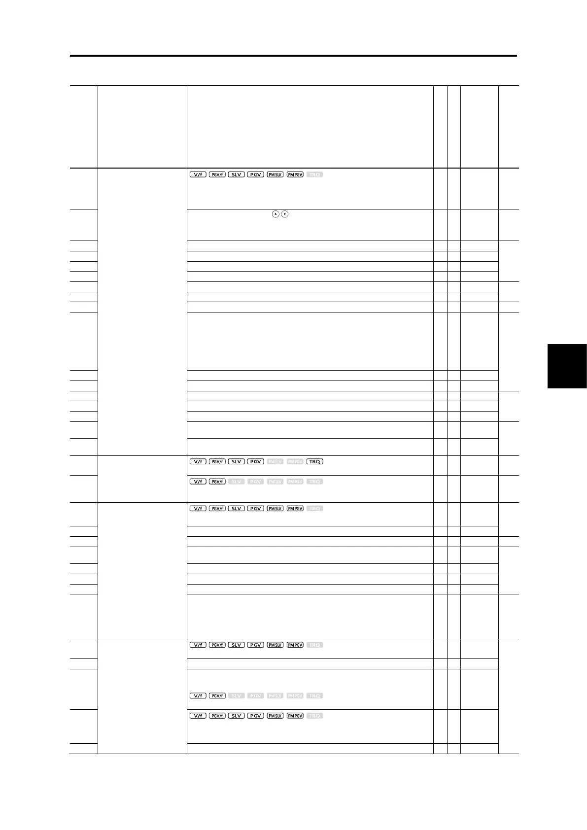
Control method and Data setting range
PID control (Mode selection)
0: Disable
1: Process (normal operation)
2: Process (inverse operation)
3: Speed control (Dancer)
0: Keypad key operation (
/
keys)
1: PID command 1 (Analog input: Terminals [12], [C1] and [V2])
3: UP/DOWN
4: Communication
(Pressurization frequency)
0: Warning caused by process command value
1: Warning caused by process command value with hold
2: Warning caused by process command value with latch
3: Warning caused by process command value with hold and latch
4: Warning caused by PID error value
5: Warning caused by PID error value with hold
6: Warning caused by PID error value with latch
7: Warning caused by PID error value with hold and latch
(Upper limit of warning (AH))
(Lower limit of warning (AL))
0.0 (Disable), 1.0 to 599.0 Hz
(Upper limit of PID process
output)
-150 % to 150 %, 999 (Based on F15)
(Lower limit of PID process
output)
-150 % to 150 %, 999 (Based on F16)
Condensation prevention
(Duty)
Switch to commercial power
supply sequence
0: Standard sequence
1: Inverter automatic switching sequence
PID control
(Wakeup level of PID error
feedback deviation)
(Dancer position set point)
(Detection width of dancer
position error)
0: Disable switching PID constant
1 to 100 %: Manually set value
(PID control block selection)
0 to 3
Bit 0: Select polarity compensation for PID output/error
0=Plus (Addition); 1=Minus (Subtraction)
Bit 1: Select compensation factor for PID output
0=Ratio (relative to the main setting)
1=Speed command (relative to maximum frequency)
Overload stop
(Item selection)
0: Disable
1: Decelerate to stop
2: Coast to stop
3: Contacting the stopper
0: During constant speed running and deceleration
1: During constant speed running
2: Anytime

 Loading...


