5.2 Function Code Tables
5-25
Function
Code Tables
F codes
E codes
C codes
P codes
H codes
A codes
b codes
r codes
J codes
d codes
U codes
y codes
Chapter 5 Function Code
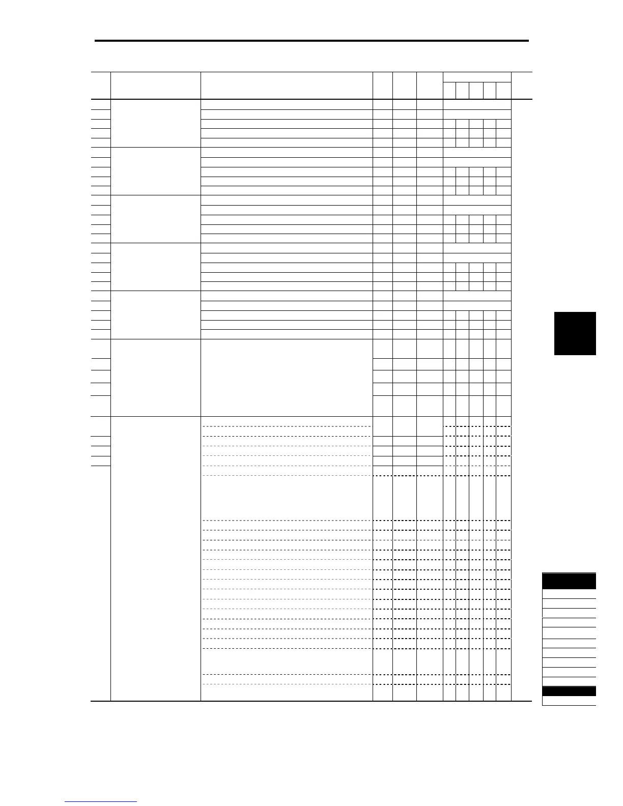
Drive control
Code Name Data setting range
Change
when
running
Data
copying
Default
setting
V/f
PG
V/f
w/o
PG
w/
PG
To rq ue
control
Refer to
page:
U26 Customizable Logic: (Input 1) See U01. N Y 0 See U01. 5-249
U27 Step 6 (Input 2) See U02. N Y 0 See U02.
U28 (Logic circuit) See U03. N Y 0 Y Y Y Y Y
U29 (Type of timer) See U04. N Y 0 Y Y Y Y Y
U30 (Time setting) See U05. N Y 0.00 Y Y Y Y Y
U31 Customizable Logic: (Input 1) See U01. N Y 0 See U01.
U32 Step 7 (Input 2) See U02. N Y 0 See U02.
U33 (Logic circuit) See U03. N Y 0 Y Y Y Y Y
U34 (Type of timer) See U04. N Y 0 Y Y Y Y Y
U35 (Time setting) See U05. N Y 0.00 Y Y Y Y Y
U36 Customizable Logic: (Input 1) See U01. N Y 0 See U01.
U37 Step 8 (Input 2) See U02. N Y 0 See U02.
U38 (Logic circuit) See U03. N Y 0 Y Y Y Y Y
U39 (Type of timer) See U04. N Y 0 Y Y Y Y Y
U40 (Time setting) See U05. N Y 0.00 Y Y Y Y Y
U41 Customizable Logic: (Input 1) See U01. N Y 0 See U01.
U42 Step 9 (Input 2) See U02. N Y 0 See U02.
U43 (Logic circuit) See U03. N Y 0 Y Y Y Y Y
U44 (Type of timer) See U04. N Y 0 Y Y Y Y Y
U45 (Time setting) See U05. N Y 0.00 Y Y Y Y Y
U46 Customizable Logic: (Input 1) See U01. N Y 0 See U01.
U47 Step 10 (Input 2) See U02. N Y 0 See U02.
U48 (Logic circuit) See U03. N Y 0 Y Y Y Y Y
U49 (Type of timer) See U04. N Y 0 Y Y Y Y Y
U50 (Time setting) See U05. N Y 0.00 Y Y Y Y Y
U 71 Customizable Logic
Output signal 1 (Output selection)
N Y 0 Y Y Y Y Y
U 72 Output signal 2 (Output selection) N Y 0 Y Y Y Y Y
U 73 Output signal 3 (Output selection) N Y 0 Y Y Y Y Y
U 74 Output signal 4 (Output selection) N Y 0 Y Y Y Y Y
U 75 Output signal 5 (Output selection)
0: Disable
1: Output of step 1 (SO01)
2: Output of step 2 (SO02)
3: Output of step 3 (SO03)
4: Output of step 4 (SO04)
5: Output of step 5 (SO05)
6: Output of step 6 (SO06)
7: Output of step 7 (SO07)
8: Output of step 8 (SO08)
9: Output of step 9 (SO09)
10: Output of step 10 (SO10)
N Y 0 Y Y Y Y Y
U 81
0 (1000): Select multi-frequency (0 to 1 step) (SS1) N Y 100 Y Y Y Y N
Customizable Logic
Output signal 1 (Function selection)
1 (1001): Select multi-frequency (0 to 3 steps) (SS2) Y Y Y Y N
U82 Output signal 2 (Function selection) 2 (1002): Select multi-frequency (0 to 7 steps) (SS4) N Y 100 Y Y Y Y N
U83 Output signal 3 (Function selection) 3 (1003): Select multi-frequency (0 to 15 steps) (SS8) N Y 100 Y Y Y Y N
U84 Output signal 4 (Function selection) 4 (1004): Select ACC/DEC time (2 steps) (RT1) N Y 100 Y Y Y Y N
U85 Output signal 5 (Function selection) 5 (1005): Select ACC/DEC time (4 steps) (RT2) N Y 100 Y Y Y Y N
6 (1006): Self-hold (HLD) Y Y Y Y Y
7 (1007): Coast to a stop (BX) Y Y Y Y Y
8 (1008): Reset alarm (RST) Y Y Y Y Y
9 (1009): Enable external alarm trip (THR)
(9 = Active OFF, 1009 = Active ON)
Y Y Y Y Y
10 (1010): Ready for jogging (JOG) Y Y Y Y N
11 (1011): Select frequency command 2/1 (Hz2/Hz1) Y Y Y Y N
12 (1012): Select motor 2 (M2) Y Y Y Y Y
13: Enable DC braking (DCBRK) Y Y Y Y N
14 (1014): Select torque limiter level 2/1 (TL2/TL1) Y Y Y Y Y
15: Switch to commercial power (50 Hz) (SW50) Y Y N N N
16: Switch to commercial power (60 Hz) (SW60) Y Y N N N
17 (1017): UP command (UP) Y Y Y Y N
18 (1018): DOWN command (DOWN) Y Y Y Y N
20 (1020): Cancel PID control (Hz/PID) Y Y Y Y N
21 (1021): Switch normal/inverse operation (IVS) Y Y Y Y N
22 (1022): Interlock (IL) Y Y Y Y Y
23 (1023): Cancel torque control (Hz/TRQ) N N N N Y
24 (1024): Enable communications link via RS-485 or fieldbus (optional)
(LE)
Y Y Y Y Y
25 (1025): Universal DI (U-DI) Y Y Y Y Y
26 (1026): Enable auto search for idling motor speed at starting (STM) Y Y Y N Y
30 (1030): Force to stop (STOP)
(30 = Active OFF, 1030 = Active ON)
Y Y Y Y Y

 Loading...


