5.4 Details of Function Codes
5-171
Details of
Function Codes
F codes
E codes
C21 to C88
P codes
H codes
A codes
b codes
r codes
J codes
d codes
U codes
y codes
Chapter 5 Function Code
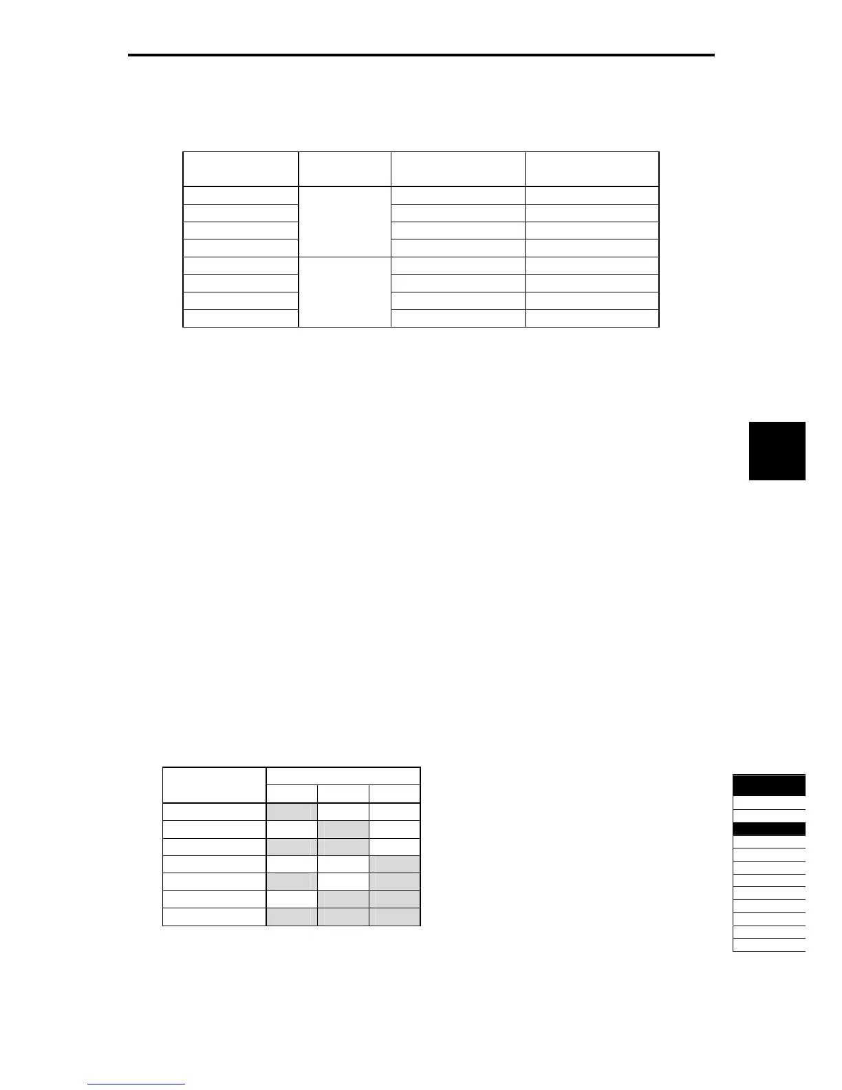
Pattern operation (Stage 1 to 7 Rotation direction, accelerate/decelerate time) (C82 to C88)
Set the rotation direction and accelerate/decelerate time of stages 1 to 7.
Table 5.4-97
C82 to C88: Set value Rotational
direction
Acceleration time Deceleration time
1 F07 Acceleration Time 1 F08 Deceleration Time 1
2 Forward E10 Acceleration Time 2 E11 Deceleration Time 2
3 E12 Acceleration Time 3 E13 Deceleration Time 3
4 E14 Acceleration Time 4 E15 Deceleration Time 4
11 F07 Acceleration Time 1 F08 Deceleration Time 1
12 Run reverse E10 Acceleration Time 2 E11 Deceleration Time 2
13 E12 Acceleration Time 3 E13 Deceleration Time 3
14 E14 Acceleration Time 4 E15 Deceleration Time 4
Multi-frequency 1 to 7 (Stage 1 to 7 Set Frequency) (C05 to C11)
Set the frequency of Stages 1 to 7.
When validating the pattern operation with F01/C30, multi-frequency command becomes invalid.
- Data setting range: 0.00 to 500.0 (Hz)
Pattern operation stage change TU (Function code E20 to E24, E27 data = 16)
During the stage change in the pattern operation, the ON signal of one shot (100 ms) is output to indicate
that the stage has been changed. Used by the customizable logic.
Pattern operation cycle operation complete T0 (Function code E20 to E24, E27 data = 17)
When all stages from 1 to 7 in the pattern operation are completed, the ON signal of one shot (100 ms) is
output. Used by the customizable logic.
Pattern operation stages No. 1, 2, 4 STG1, STG2, and STG4 (Function codes E20 to E24, E27 data = 18,
19, 20)
During the pattern operation, the currently-operating stage is output.
Table 5.4-98
Output Terminal Signal Operation Pattern
Stage No.
STG1 STG2 STG4
Stage 1 ON OFF OFF
Stage 2 OFF ON OFF
Stage 3 ON ON OFF
Stage 4 OFF OFF ON
Stage 5 ON OFF ON
Stage 6 OFF ON ON
Stage 7 ON ON ON

 Loading...


