App. G Replacement Information
A-34
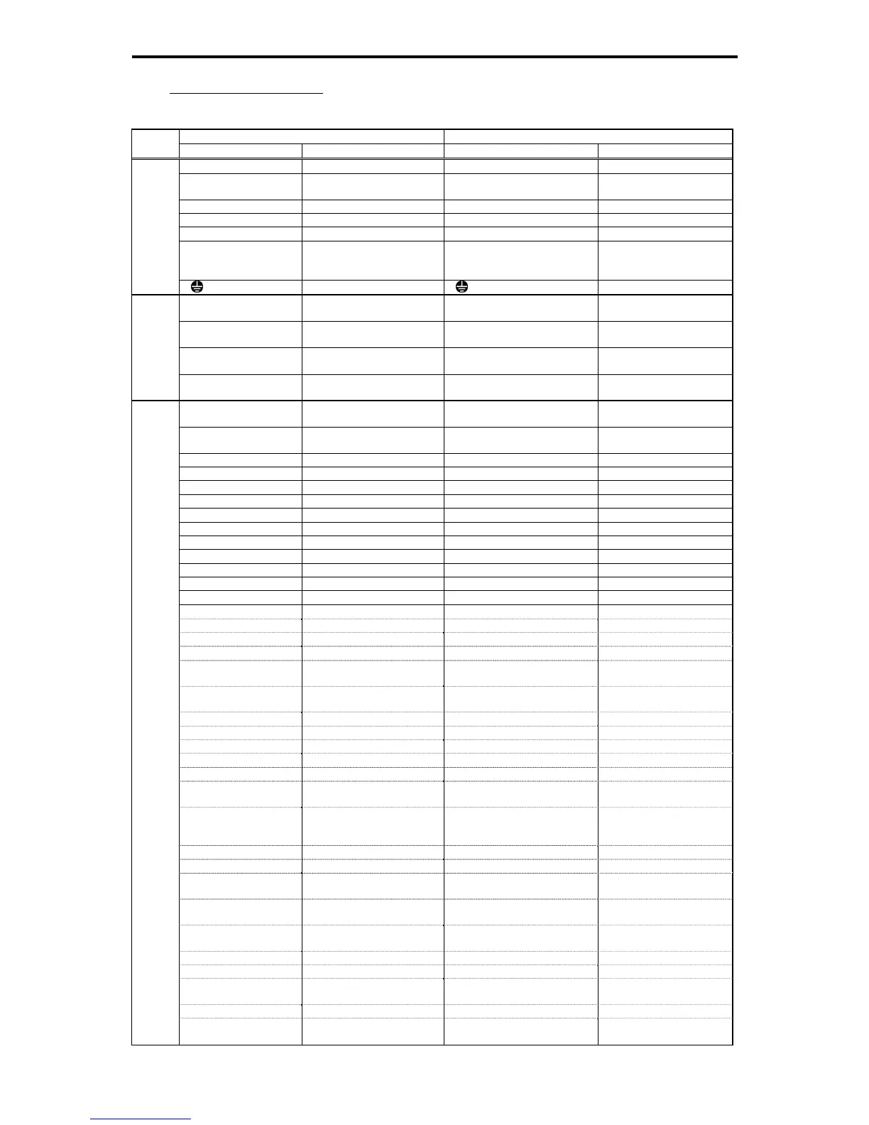
vs. FRENIC5000G11S/P11S
Table G-9
FRENIC5000G11S/P11S FRENIC-MEGA
Class
Terminal Signal Name Terminal Signal Name
L1/R, L2/S, L3/T Main circuit power inputs L1/R, L2/S, L3/T Main circuit power inputs
R0, T0
Auxiliary power input for the
control circuit
R0, T0
Auxiliary power input for
the control circuit
U, V, W Inverter outputs U, V, W Inverter outputs
P1, P(+) DC reactor connection P1, P(+) DC reactor connection
P(+), N(-) DC link circuit terminal P(+), N(-) DC link bus
P(+), DB
External braking resistor
connecting terminal
(Up to 22 kW)
P(+), DB Braking resistor
Main circuit
G
Grounding for inverter G
Grounding for inverter
13
Power supply for the
potentiometer
13
Power supply for the
potentiometer
12
Frequency setting voltage
input
12
Frequency setting voltage
input
C1
Frequency setting current
input
C1
Frequency setting current
input
Analog input
11 Analog common
Analog input common 11 (2
terminals)
Analog common
FWD Run forward/stop command FWD
Run forward/stop
command
REV Run reverse/stop command REV
Run reverse/stop
command
X1 Digital input 1 X1 Digital input 1
X2 Digital input 2 X2 Digital input 2
X3 Digital input 3 X3 Digital input 3
X4 Digital input 4 X4 Digital input 4
X5 Digital input 5 X5 Digital input 5
X6 Digital input 6 X6 Digital input 6
X7 Digital input 7 X7 Digital input 7
X8 Digital input 8 X8 Digital input 8
X9 Digital input 9 X9 Digital input 9
CM Digital input common CM (2 terminals) Digital input common
PLC PLC signal power PLC PLC signal power
(SS1) Multi-frequency selection SS1 Multi-frequency selection
(SS2) SS2
(SS4) SS4
(SS8) SS8
(RT1)
Select ACC/DEC time (2
steps)
RT1
Select ACC/DEC time (2
steps)
(RT2)
Select ACC/DEC time (4
steps)
RT2
Select ACC/DEC time (4
steps)
(HLD) Self hold selection HLD Self hold selection
(BX) Coast-to-stop command BX Coast-to-stop command
(RST) Error reset RST Reset alarm
(THR) External alarm THR External alarm
(JOG) Jogging operation JOG Jogging operation
(Hz2/Hz1)
Frequency setting 2/
Frequency setting 1
Hz2/Hz1
Frequency setting 1/
Frequency setting 2
(Hz1/Hz2)
Frequency setting 1/
Frequency setting 2
Hz2/Hz1
Frequency setting 2/
Frequency setting 1
(negative logic setting)
(M2/M1) Motor 2/motor 1 M2 Select motor 2
(DCBRK) Enable DC braking DCBRK Enable DC braking
(TL2/TL1)
Torque limiter 2/
Torque limiter 1
TL2/TL1
Torque limiter 2/
Torque limiter 1
(SW50)
Switch to commercial power
(50Hz)
SW50
Switch to commercial
power (50 Hz)
(SW60)
Switch to commercial power
(60 Hz)
SW60
Switch to commercial
power (60 Hz)
(UP) UP command UP UP command
(DOWN) DOWN command DOWN DOWN command
(WE-KP)
Enable data change with
keypad (WE-KP)
WE-KP
Enable data change with
keypad (WE-KP)
(Hz/PID) Cancel PID control Hz/PID Cancel PID control
Digital input
(IVS)
Switch normal/inverse
operation
IVS
Switch normal/inverse
operation

 Loading...


