Product Overview
40
Product Overview
2
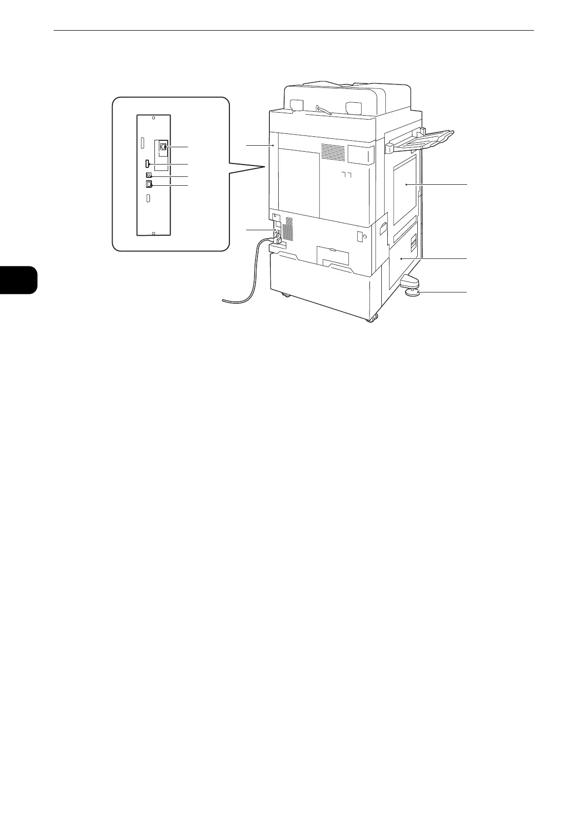
Left side and rear views of the machine
1 Upper left cover
Open this cover by lifting up the release lever to clear paper jams.
2 Bottom left cover
Open this cover to clear paper jams. When Tray 6 is installed, open this cover after moving
Tray 6 to the left.
3 Adjusting foot
Prevents the machine from toppling over. Move the machine to its installation site and then
rotate this adjuster in clockwise direction until it touches a floor.
4 RESET button
Automatically switches the machine off when a current leakage is detected.
5 Rear right cover
Make sure that this cover is attached. Open this cover when connecting an interface cable.
6 Ethernet interface connector
Connects to a network cable.
7 USB 3.0 interface connector
Connects a USB memory cable for printing.
8 USB 2.0 interface connector
Connects to the cable of the Memory Card Reader or a USB memory device.
z
The Memory Card Reader and a USB memory device cannot be connected to the machine at the same time.
The machine will recognize the one that is connected first.
9 Secondary Ethernet connector (optional)
Connects to a network cable.
This view varies depending on the
model you use.
 Loading...