5.5.7.2 Humidier Disassembly
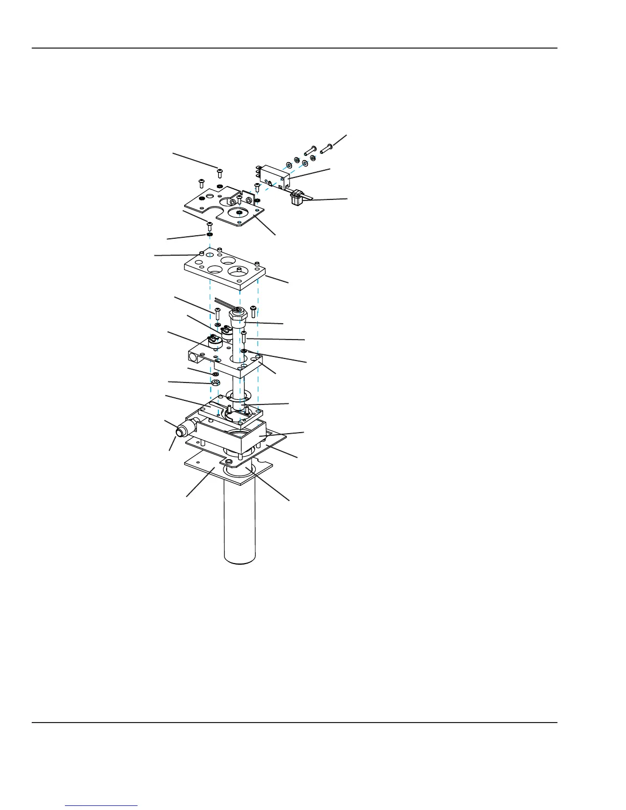
Refer to “Figure 5-4 Chassis Bottom Cover” and “Figure 5-10 Humidier Parts”.
Insulating cylinder
Heater cartridge
Add water thermostat
Safety thermostat
Reservoir switch
Top bracket
Top gasket
Heater mount
Heater cartridge sheath
Spacer
Ramp block
M3 x 12 Phillips head screw
(Attaches ground wire with two
star washers)
Reservoir switch button
Steam outlet
Silicone tube
M3 x 10 Phillips head coated screw
Split ring washer
6-32 Hex nut
Split ring washer
M3 x 10 Phillips head
coated screw
Protective insert
M3 x 10 socket
head cap screw
Star washer
Bottom gasket
Bottom bracket
Reservoir seal
M3 x 16 Phillips head screw
Figure 5-10 Humidier Parts
1. Remove the humidier reservoir.
2. Remove the 6 screws that secure the wire raceway cover and remove the cover.
3. Remove the chassis cover. (Refer to section 5.5.1.)
4. Disconnect the 3 electrical connectors.
82 6600-0356-000 103 © 2001 by Datex-Ohmeda, Inc.. All rights reserved.
Chapter 5: Repair Procedures