RT2
1 2
t
1
2
3
4
5
6
RT7
1 2
t
RT1
1 2
t
1
2
3
4
1
2
3
4
5
1
2
3
4
5
6
7
8
1
2
3
4
5
6
7
8
1
2
3
4
5
6
7
J6.1
J6.2
J6.3
J6.4
J6.5
J6.6
J5.1
J5.2
J5.3
J5.4
J10.1
J10.2
J10.3
J10.4
J10.5
J7.1
J7.2
J7.3
J7.4
J7.6
J7.7
TP1.1 1.2 V ind
TP1.3 V thref
TP1.4 - 5 VAN
TP2.1 + 5 V
TP2.2 AUDIO_FREQ
TP2.3 + 5 V STBY
TP2.4 GND (D)
TP1.6 GND (A)
TP1.5 + 5 VAN
J9.7
J9.3
J9.8
J9.4
J9.6
J9.2
J9.5
J9.1
J9.10
J9.11
J9.18
J9.14
J9.19
J9.15
J9.17
J9.13
J9.16
J9.12
J9.20
J9.21
J9.24
J9.23
J9.22
J9.9
JP1.1
JP1.3
JP1.4
J1.1
J1.2
J1.3
J1.4
J1.5
J1.6
J1.7
J4.1
J4.2
J4.3
J4.4
J2.1
J2.2
J2.3
J3.1
J3.2
J9.25
J9.26
J9.27
J9.31
J9.28
J9.29
J9.30
J9.35
J9.36
J9.34
J9.32
J9.37
J9.38
J9.40
J9.39
J9.43
J9.42
J9.41
J9.33
J9.50
J9.49
J9.48
J9.47
J9.46
J9.45
J9.44
J8.12
J8.13
J8.14
J7.5
J8.11
J8.10
J8.9
J8.8
J8.7
J8.6
J8.5
J8.4
J8.3
J8.2
J8.1
JP1.5
JP1.6
JP1.7
JP1.2
JP1.8
TP1.2 1.2 V
J10.6
1
2
3
4
5
6
1
2
RT2
1 2
t
1
2
3
1
2
3
2
1
5
6
3
7
1
2
3
4
5
6
1
2
3
4
5
6
1
2
3
1
2
3
4
5
6
7
8
RT4
1 2
t
1
2
3
4
5
1
2
3
4
5
6
7
8
SCALE
1
2
3
4
5
6
7
8
1
2
RT5
1 2
t
RT1
1 2
t
RT6
1 2
t
1
2
3
4
RT3
1 2
t
1
2
3
4
5
6
7
8
1
2
3
4
5
6
7
8
1
2
3
4
5
6
1
2
3
4
5
6
7
8
9
NURSE CALL_1
JP1.5
JP1.6
JP1.7
JP1.8
JP1.3
JP1.2
JP1.4
JP1.1
JP1.9
JP2.6
JP2.5
JP2.4
JP2.3
JP2.1
JP2.2
1
2
3
4
1
2
3
GND
GND
GND
E/H ACTIVATE
SYSFAIL
+12V
MOTORHALLSENSOR
S_RELAY
SEC_SAFETY_RELAY
AIRFLOW
RHADDWATER
EBASEDOWN
SPKR+
A
GND
GND
B
EBASE_STALL
INC/WARMCURRENTSENSE
MOTORSPEED
INVERTPOLARITY
GND
GND
GND
GND
GND
GND
SPKR+
RHBOTTLE
RHCURRENTSENSE
+5VSTBY
SPKR-
+5V
SPKR-
E/H SELECT
GND
GND
EBASEUP
ALM_LED
MOTORBRAKE
GND
RHHEAT
/INT
GND
LINE_COMP
GND
MOTORCURRENT
LINEFREQUENCY
GND
24VOLTSELECT
GND
INC_HEAT
MODULE_RESET
brown
shield
Humidity Sensor
(bottom view)
brown
RXD1
Call Open (No Alarm)
Heatsink Thermistor
brown
yellow
/SYSFAIL
red
yellow
MODULE RESET
green
6600-0719-700
white
brown
6600-0784-700
Jumper
black
green
+12V
yellow
black
B
normal
mode
NO CONNECT
Relay Board
NO CONNECT
yellow
blue
calibrate
mode
red
orange
green
A
+5V
Transmit Line 2
yellow
red
black
red
orange
6600-1226-600
green
blue
orange
brown
6600-0702-700
brown
shield
RH SIG
black
black
6600-1513-700
6600-0716-701
white
red
yellow
blue
blue
green
orange
black
blue
red
Expansion Slots
orange
yellow
shield
6600-0742-700
brown
brown
/INT
red
black
Call Closed (No Alarm)
black
6600-0716-702
greenyellow
black
/SYSFAIL
orange
brown
black
brown
red
Transmit Line 1
green
6600-0241-850
GND
brown
PT 2
orange
green
TXD1
+5V
orange
GND
MODULE RESET
6600-0704-700
brown
Receive Line
NO CONNECT
black
ISO GND
CASE GND
Call Common
To J42 on
6600-0530-700
blue
B
blue
red
green
orange
GND
CALL
Connection to
Humidity Sensor
blue
6600-0783-700
Environmental Connector viewed
from wire termination side of
panel connector
6600-0822-700
GND
red
yellow
Environmental Sensor for Systems with Panel Connector
red
A
PT 1
blue
Environmental Sensor for Systems without Panel Connector
6600-0226-850
red
6600-0701-700
white
black
blue
/INT
Scale Connector viewed
from wire termination
side of panel connector
Control Board
Replacement Kit
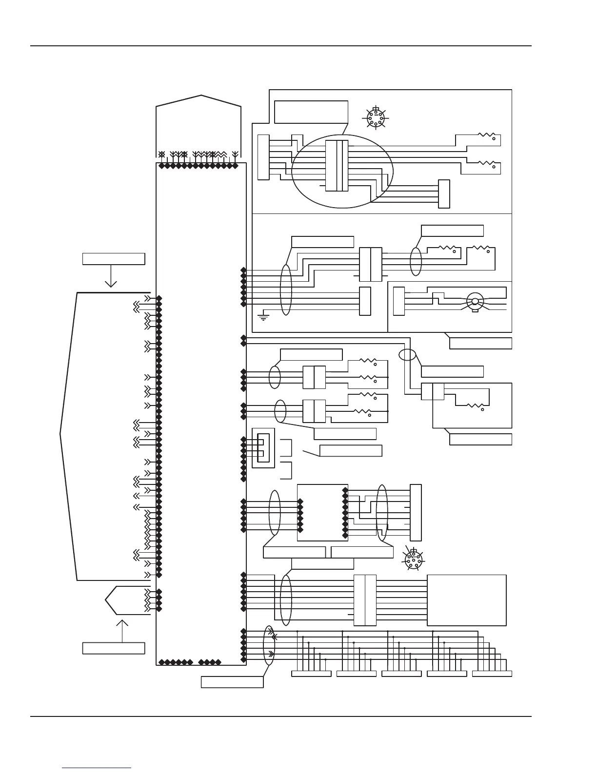
Figure 6-36 Wiring Diagram: Control Board
6.5 Wiring Diagrams
156 6600-0356-000 103 © 2001 by Datex-Ohmeda, Inc.. All rights reserved.
Chapter 6: Illustrated Parts