Item Description
Cal Scale
Brings up scale calibration screen. Refer to “Chapter 3: Calibration and Maintenance” for
information on how this screen is used.
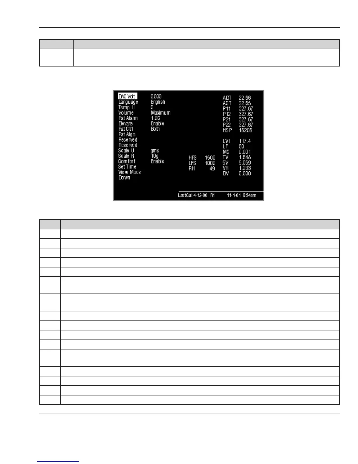
A number of diagnostic readings appear on the right side of the service screens.
Figure 4-5 First Service Screen: Diagnostics
Item Description
HFS High fan speed. Should be 1500 + 100 (measured at power up only)
LFS Low fan speed. Should be 1000 + 100 (measured at power up only)
RH Relative Humidity. % humidity read in the patient chamber
SR Scale counts raw
SC Scale counts corrected (1 count = 1 gram)
ADT
Air display temperature. Temperature read by the rst thermistor in the compartment air probe.
Should be + 0.3ºC of ACT temperature.
ACT
Temperature read by second thermistor in the compartment air probe. Should be + 0.3ºC of ADT
temperature.
P11 Reading from the rst thermistor in patient jack 1. Should be + 0.5ºC of P12 temperature.
P12 Reading from the second thermistor in patient jack 1. Should be + 0.5ºC of P11 temperature.
P21 Reading from the rst thermistor in patient jack 2. Should be + 0.5ºC of P22 temperature.
P22 Reading from the second thermistor in patient jack 2. Should be + 0.5ºC of P21 temperature.
HSP
Heat sink sensor resistance. Should be approximately 20000 ohms @ 25ºC. Refer to the Tips section
4.6.7 for resistance verses temperature values.
LV1 Line voltage in rst mains circuit.
LF 60Hz or 50Hz
MC Motor current. Shows current drawn by the e-base motor
TV Thermistor voltage. Voltage of thermistor circuits located on the mother board.
© 2001 by Datex-Ohmeda, Inc.. All rights reserved. 6600-0356-000 103 31
Chapter 4: Troubleshooting