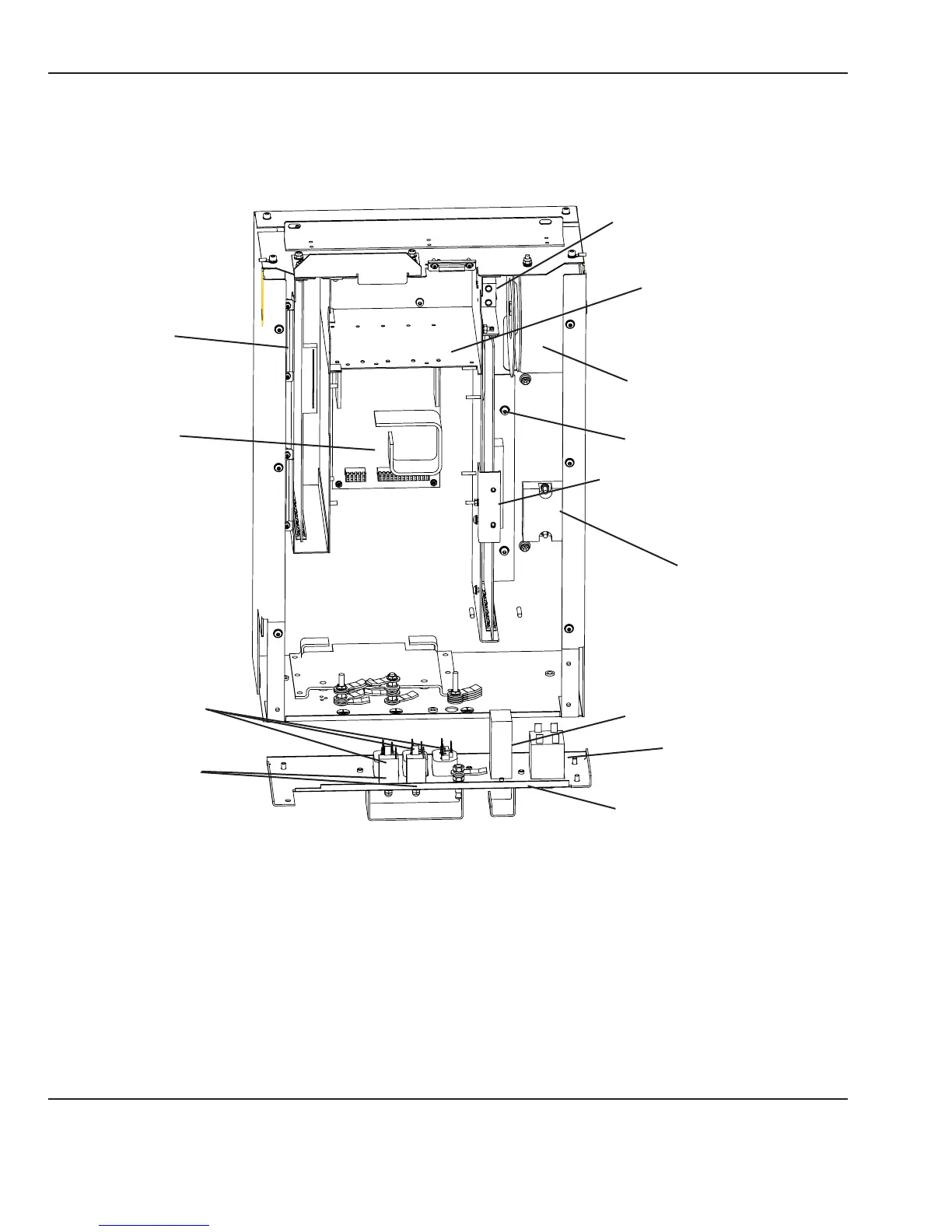
5.8.3 Controller Components
Refer to “Figure 5-14 Electronics Enclosure”.
Control board
Power supply
Circuit breakers
Power outlets
Line lter
Power switch
Solid state relay
Relay board
Toroidal transformer
Battery (In newer units, the
battery is in the probe panel
housing.)
Connection panel
Card cage
Relay board retainer bracket
Figure 5-14 Electronics Enclosure
Using a 2.5 mm hex key, loosen the 2 screws in the keyhole slots and remove the 6 remaining screws that
secure the controller cover, then remove the cover. Now you can access the electrical components listed below.
90 6600-0356-000 103 © 2001 by Datex-Ohmeda, Inc.. All rights reserved.
Chapter 5: Repair Procedures