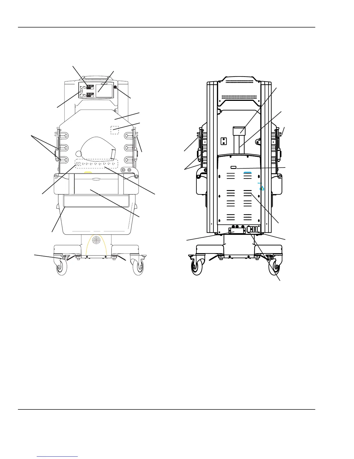
2.7 Cable Connections and Mechanical Controls
Numeric Temperature Displays
Temperature
Regulation
Controls
Graphics Screen
Tubing
Grommets
Standby
Power
Switch
(I/O)
Drainage
Hanger
Caster
Brake
FRONT
Control Knob
Hood
Probe Jacks
Humidier Reservoir
(air intake lter located
behind reservoir)
Accessory
Power Outlets
Ventilator
Slot
Mains Power
Switch
RS 232
Connector
Tubing
Grommets
Side Door
Latch
BACK
Controller
Cover
Side Door Latch
Compartment Probe
Power
Cord
Inlet
Tubing access
door
Figure 2-1 Connections and Controls
16 6600-0356-000 103 © 2001 by Datex-Ohmeda, Inc.. All rights reserved.
Chapter 2: Service Checkout