P
N
G
1
2
3
4
5
6
P
N
G
1
2
3
4
5
1
2
3
1
2
3
SPEAKER
EBASE MOTOR
M
P
N
G
UP
P
N
G
UP
1
2
3
4
5
1 2 13
24
1
2
1
2
3
4
5
6
1 2
1
2
3
4
5
1
2
3
4
5
DOWN
DOWN
GND
Relay
Board
SPKR+
shield
white
green
SPKR-
6600-0883-700 (X2)
red
Ebase Left/West Foot
white
orange
red
6600-0750-700
brown
brown
yellow
6600-0753-701
black
blue
Base Pedestal
Ebase Right/East Foot
brown
green
West Rail Ground
black
Relay Board
black
red
6600-0285-850
To J45 on
6600-0285-850
6600-0713-700
red
EBASEDOWN
orange
East Rail Ground
EBASEUP
black
6600-0715-700
shield
HOODPEDAL
6600-1168-600
To J40
on
brown
No
Connection
J40.1
J40.2
J40.3
J40.4
J40.5
J40.6
J45.1
J45.2
6600-0870-700
Bed Chassis
6600-0863-700 (X2)
Heatsink Ground
Cover Ground
Ground Equalization Post
Ground Wires
To J51 on
6600-0731-700
Power Switch/
Circuit Breaker
Relay Board
blue
6600-0562-603 X2
Mains Outlets
Line Filter
6600-1014-601 (9 Amp, 230V)
6600-1014-602 (12 Amp, 115V)
Outlets
J51.3
brownJ51.1
6600-0583-600 (X3)
6600-1006-600
includes wiring to outlets
Circuit Breakers 3.5A.
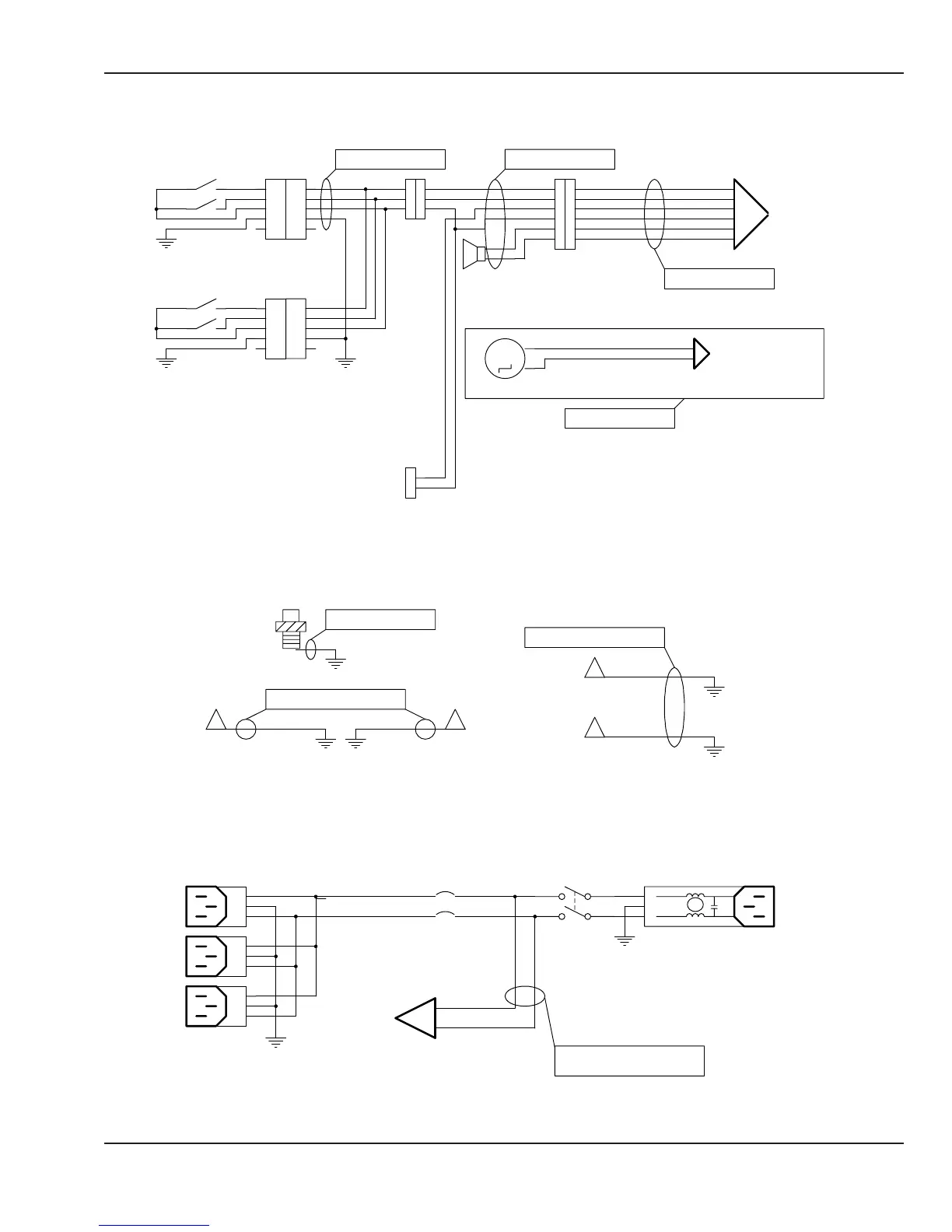
Figure 6-37 Wiring Diagram: Elevating Base
© 2001 by Datex-Ohmeda, Inc.. All rights reserved. 6600-0356-000 103 157
Chapter 6: Illustrated Parts