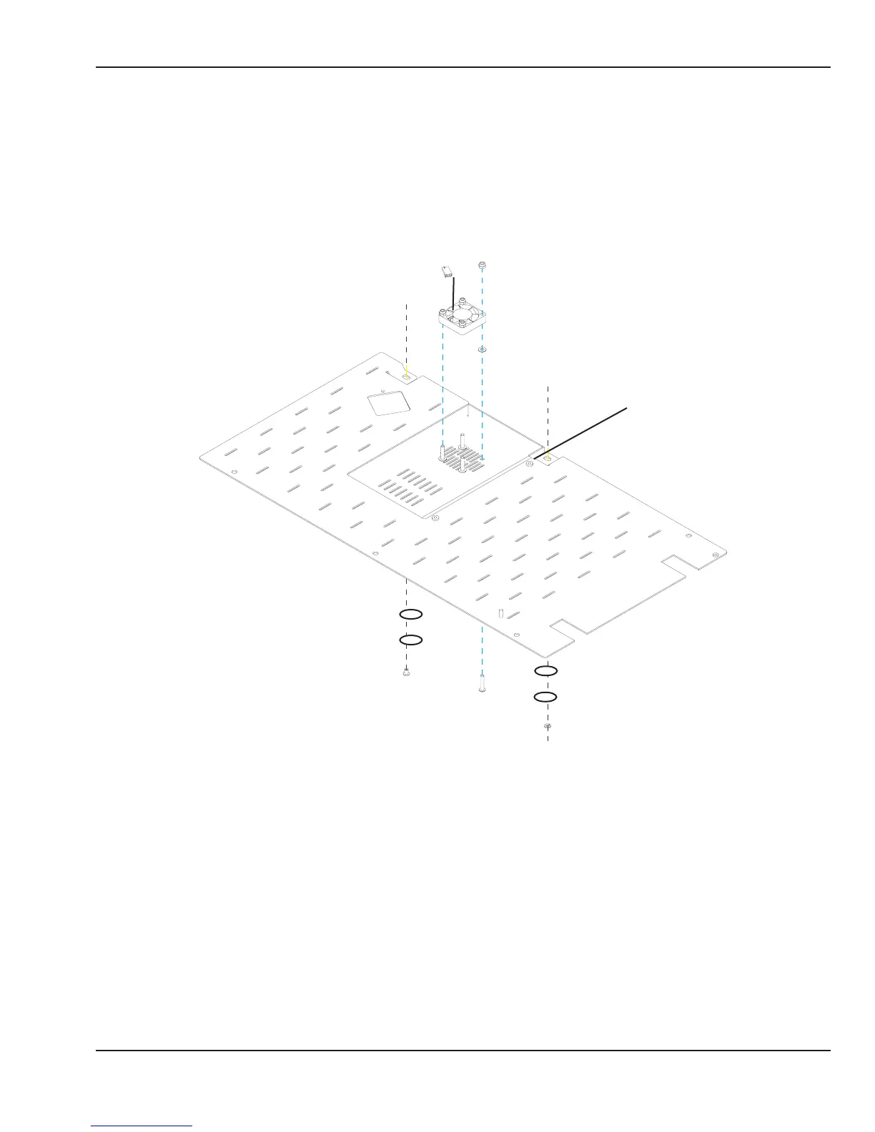
1. Nyloc nut, M4 ......................................................................6600-0714-402
2. Cooling fan assembly* ....................................................6600-1523-700
3. Flat washer, M4...................................................................6600-0712-403
4. Screw, M4x20L Button Hd .............................................6600-0706-412
5. Screw, captive 8mm long ..............................................6600-0868-401
6. Screw, SEMS M4 x 6 Button Hd ...................................6600-0908-402
Parts not shown
Cable tie .................................................................................6600-0384-400
* Install fan so ow arrow on side points down, away from chassis.
1
2
3
4
5
6
Figure 6-19 Servo Control Oxygen Cooling Fan
© 2001 by Datex-Ohmeda, Inc.. All rights reserved. 6600-0356-000 103 135
Chapter 6: Illustrated Parts