4.6.3 Power Supplies
The 5V and 12V supplies are generated on the power supply. +5STBY is generated on the relay board. These
voltages are distributed to the control board, display driver board, servo oxygen board, and expansion slots
through a harness with a series of 4 pin connectors. The easiest place to measure the power supplies is at one
of the spare 4 pin connectors on this power bus.
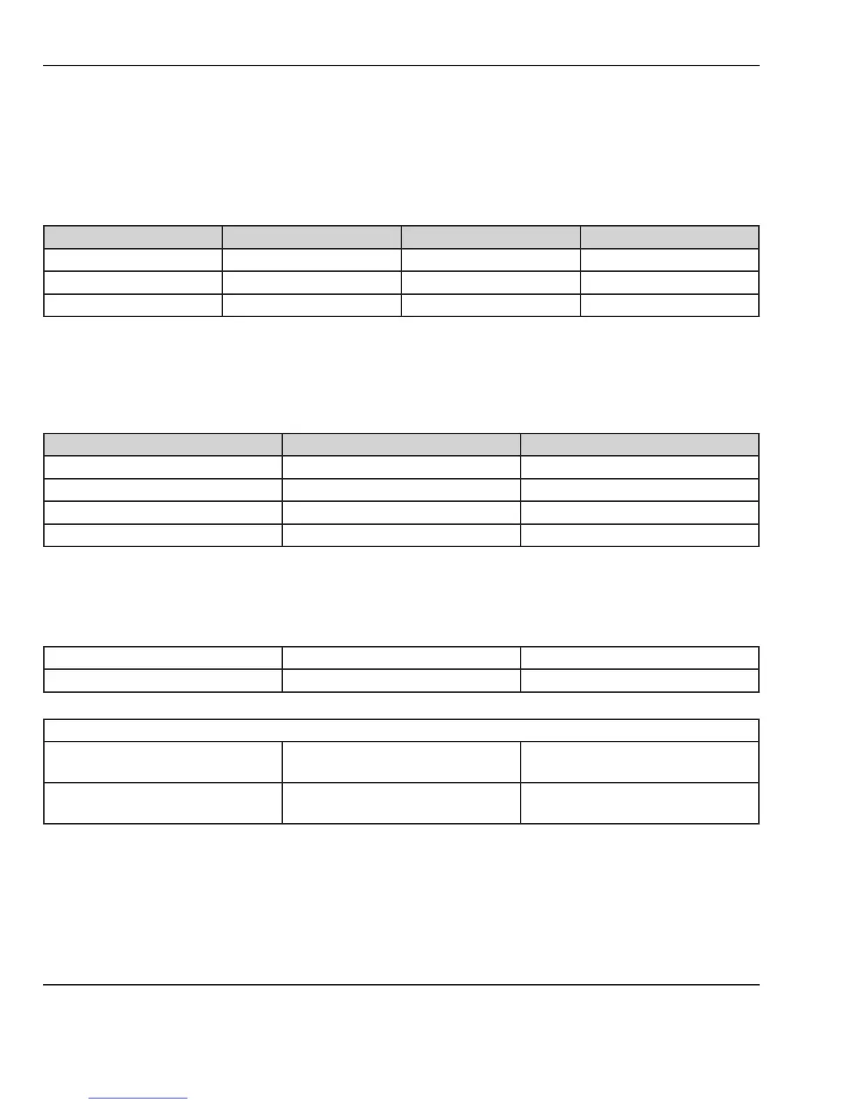
Signal Location Wire Color Value
+5V J42 pins 1-2 Orange and blue 4.75 to 5.25
+5VSTBY J42 pins 1-4 Orange and green 4.75 to 5.25
+12V J42 pins 1-3 Orange and red 10.8 to 13.2
The 5VSTBY should also be present during power fail.
+5VAN and -5VAN are generated on the control board and are only used on the control board. They can be
measured on the test points on the control board.
Signal Location Value
+5V TP2 pins 1-4 4.75 to 5.25
+5VSTBY TP2 pins 3-4 4.75 to 5.25
+5AN TP1 pins 5-6 4.75 to 5.25
-5AN TP1 pins 4-6 -4.0 to -5.5
4.6.4 Switches/Thermostat
Use switch status diagram on the second service screen to assist in troubleshooting the switches.
Humidity reservoir Relay bd J32 pins 2-3 Closed when reservoir is closed
Add water thermostat Relay bd J32 pins 1-3 Opens when reservoir needs water
Elevating base
Left or right up Relay bd J40 pins 2-4
Closed when either switch is
pressed
Left or right down Relay bd J40 pins 1-4
Closed when either switch is
pressed
54 6600-0356-000 103 © 2001 by Datex-Ohmeda, Inc.. All rights reserved.
Chapter 4: Troubleshooting