GE H
EALTHCARE
D
IRECTION
GA091568, R
EVISION
5 VIVID E9 S
ERVICE
M
ANUAL
Chapter 5 - Components and functions (theory) 5 - 27
Section 5-8
Front End Processor (FEP)
5-8-1 Front End Card Rack description
The Front End Card Cage / Card Rack with the electronics is also called the Front End Processor (FEP).
5-8-1-1 Front End Processor cards overview
NOTICE
The cards have color-keys on the connectors to prevent installation in the wrong rack position. Do not
change the color-keys position. Don’t insert a card in the wrong position in the Card Rack. If the power
is turned on with a card placed in the wrong position, the VIVID E9 will be destroyed.
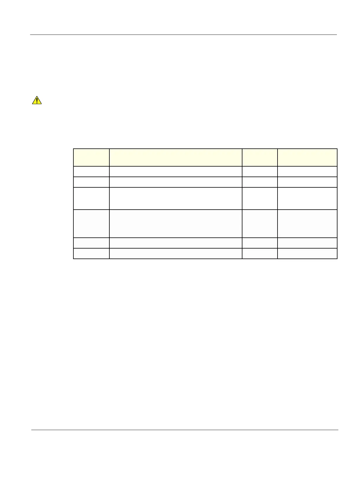
Table 5-4 The Front End Processor Card Positions
SHORT
NAME
COMPLETE NAME
MAX QTY IN
SYSTEM
COMMENT
GRLY RELAY BOARD
1
GRX RECEIVER BOARD
2
GTX TRANSMITTER BOARD
4
The number of cards in use
vary by VE9 model and card
model used.
FRONT PLANE
/ XD BUS
FRONT PLANE / TRANSDUCER BUS BOARD
2
Not shown in the illustration
above.
Two (2x) cards are always
used.
DRX DIGITAL RECEIVER BOARD
4
GFI GLOBAL RADIO FREQUENCY INTERFACE BOARD (GFI)
1