GE H
EALTHCARE
D
IRECTION
GA091568, R
EVISION
5 VIVID E9 S
ERVICE
M
ANUAL
Chapter 10 - Care & maintenance 10 - 9
10-5-4 Physical inspection
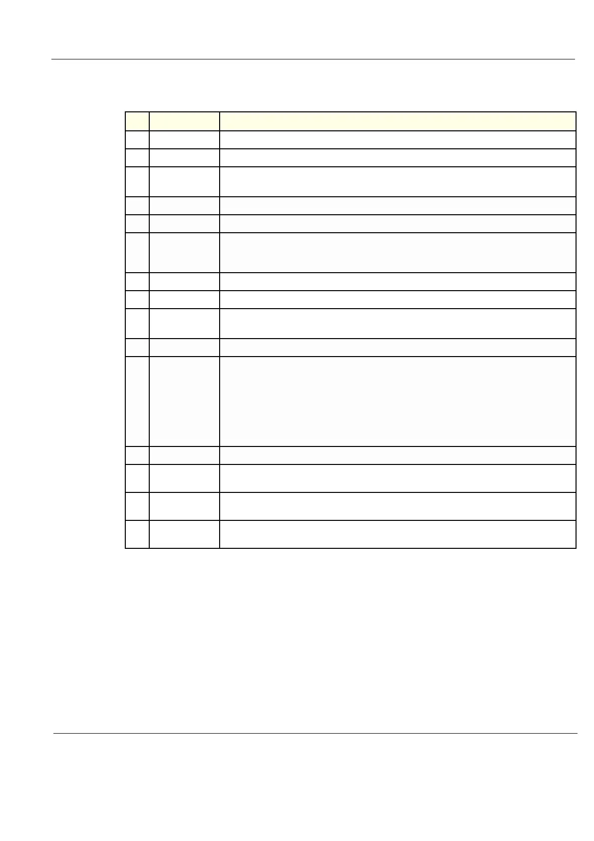
Table 10-6 Physical Checks
Step Item Description
1. Labeling Verify that all VIVID E9 labeling is present and in readable condition. .
2. Scratches & Dents Inspect the console for dents, scratches or cracks.
3. Covers
Where applicable, verify all covers are secured in place and are properly aligned with other covers.
Replace any covers that are damaged.
4. Input Power Refer to: 10-5-3-1 "Mains cable inspection" on page 10-8.
5. External I/O Check all connectors for damage and verify that the labeling is good.
6.
Wheels & Brakes
• Check all wheels and casters for wear and verify operation of foot brake, to stop the VIVID E9
from moving, and release mechanism.
• Check all wheel locks and wheel swivel locks for proper operation.
7. Op Panel Inspect keyboard and control panel. Record any damaged or missing items.
8. Probe Holders Inspect the Probe Holders for cracks or damage.
9.
Op Panel
Movement
• Verify ease of Operator Panel (Operator Control Panel) movement in all acceptable directions.
• Ensure that it latches in position as required.
10. Op Panel Lights Check for proper operation of all operator panel and TGC lights.
11.
LCD
Inspect the LCD Display for scratches and bad pixels.
Verify proper operation of Contrast and Brightness controls.
Confirm that the LCD arm allows:
• swivelling the screen to the left and to the right
• folding the screen to the locked position
• release and adjustment backwards and forwards
• can be adjusted in the up/down positions.
12. Monitor Light Check for proper operation of any monitor lighting, if available.
13. Cables and
Connectors
Check all internal cable harnesses and connectors for wear and secure connector seating.
Pay special attention to footswitch assembly and probe strain or bend reliefs.
14. Shielding and
Covers
Check to ensure that all EMI shielding, internal covers, air flow panels and screws are in place.
Missing covers and hardware could cause EMI/RFI problems while scanning.
15. Power and System
Status Indicators
Check for proper operation of all Power and System Status Indicators.