GE H
EALTHCARE
D
IRECTION
GA091568, R
EVISION
5 VIVID E9 S
ERVICE
M
ANUAL
5 - 50 Section 5-8 - Front End Processor (FEP)
5-8-9 FEP Backplane
5-8-9-1 General description
The front side of the FEP Backplane has connectors for the Front End boards (RELAY, GRX, GTX, DRX
and GFI), the Main Power Supply, the External I/O, the Fan Connector and a connector for the CW
probe signals.
On the rear side of the FEP Backplane, there is the FEP Backplane Connector with BSCAN signals,
GFI Audio, +5V (from GFI) and I
2
C signals from the FEP Backplane.
• Voltages are distributed from the Main Power Supply to the different boards.
• Control signals and Clocks are distributed from the GFI board to the other boards.
• Low amplitude analog signals from GRX board to DRX board.
• Data signals are routed from DRX board to GFI board.
• The BSCAN signals, GFI Audio, +5V (from GFI) and I
2
C signals are routed to the BEP and/or
External I/O, depending on the BEP model in use.
The only active electronics on the FEP Backplane is a I
2
C memory device for the Board Info and a
voltage regulator for the power supply to the I
2
C memory.
In addition, there are termination resistors and power supply bypass capacitors.
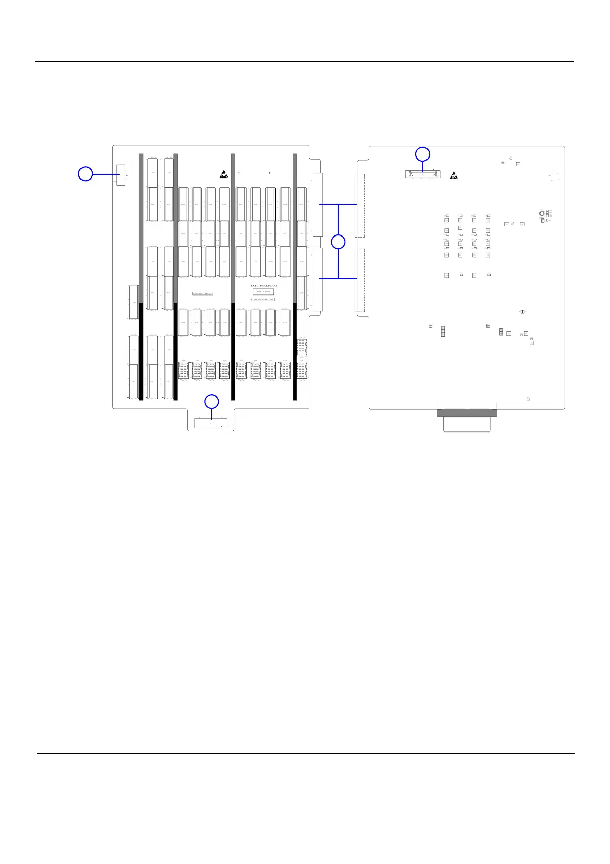
Figure 5-35 FEP Backplane
Front side of the FEP Backplane
1. CW Doppler Connector
2. Power Connectors (2x)
3. Fan Connector
Rear side of the FEP Backplane
2. Power Connectors
4. FEP Backplane Connector
1.
2.
4.
3.