GE H
EALTHCARE
D
IRECTION
GA091568, R
EVISION
5 VIVID E9 S
ERVICE
M
ANUAL
Chapter 5 - Components and functions (theory) 5 - 33
5-8-3-1 General description (cont’d)
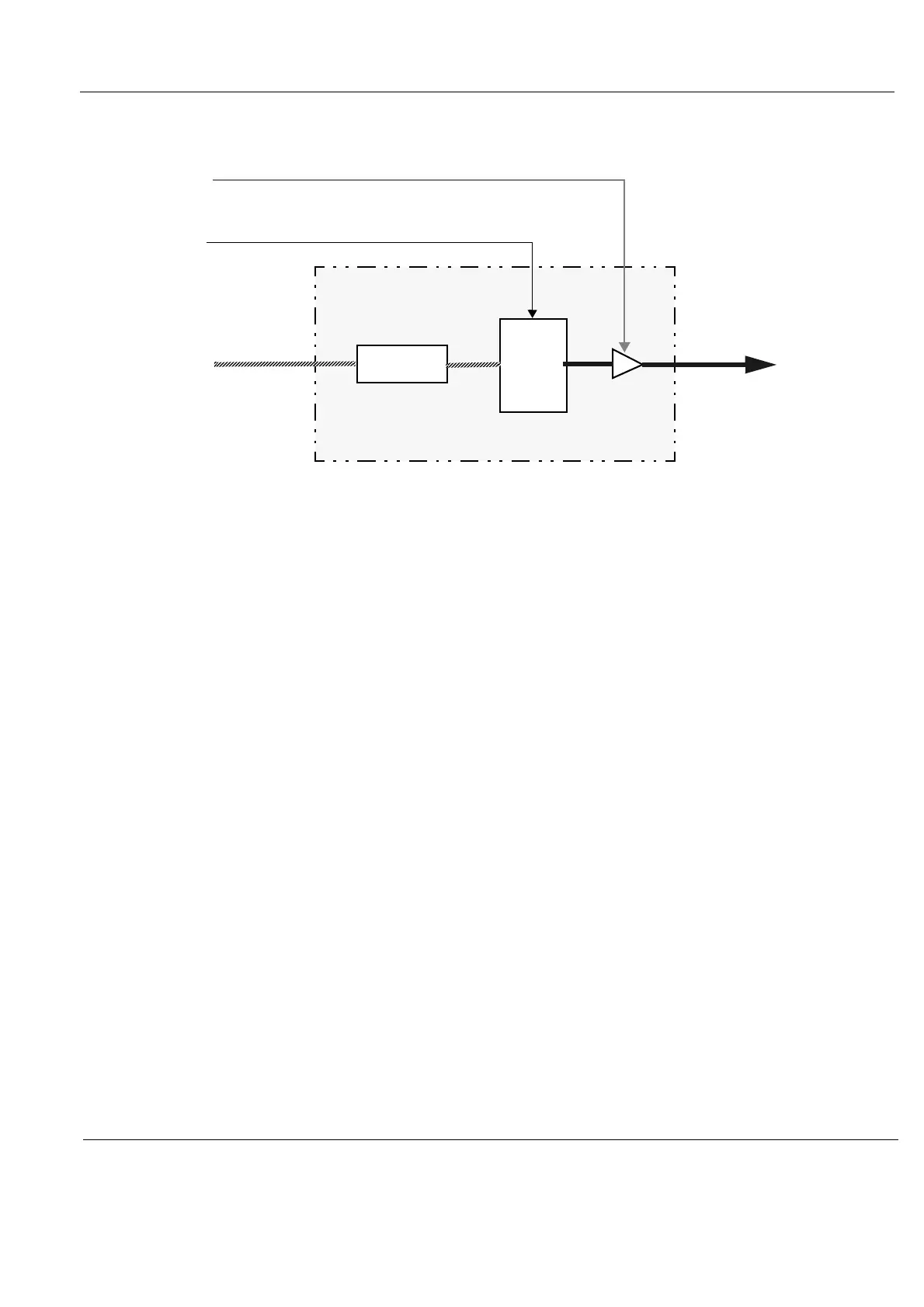
A pulse from the GFI board, TX_TRIG_L, trigs the Transmit Pulse Generators.
TS Voltage 1 and TS Voltage 2 from the Main Power Supply, supply the transmitters with the needed
voltages to generate the correct ultrasound signals.
Figure 5-18 Block Diagram for the GTX board (one channel illustrated)
FROM
TSV1&2
TX_TRIG_L
FROM GFI
FE_BUS
XD1-n
TO RLY VIA XDBUS
TSV1P
TSV2P
TSV2N
TSV1N
FROM GFI
FRONT END
INTERFACE
TRANSMIT
PULSE
GEN.
TX
MAIN POWER SUPPLY