GE H
EALTHCARE
D
IRECTION
GA091568, R
EVISION
5 VIVID E9 S
ERVICE
M
ANUAL
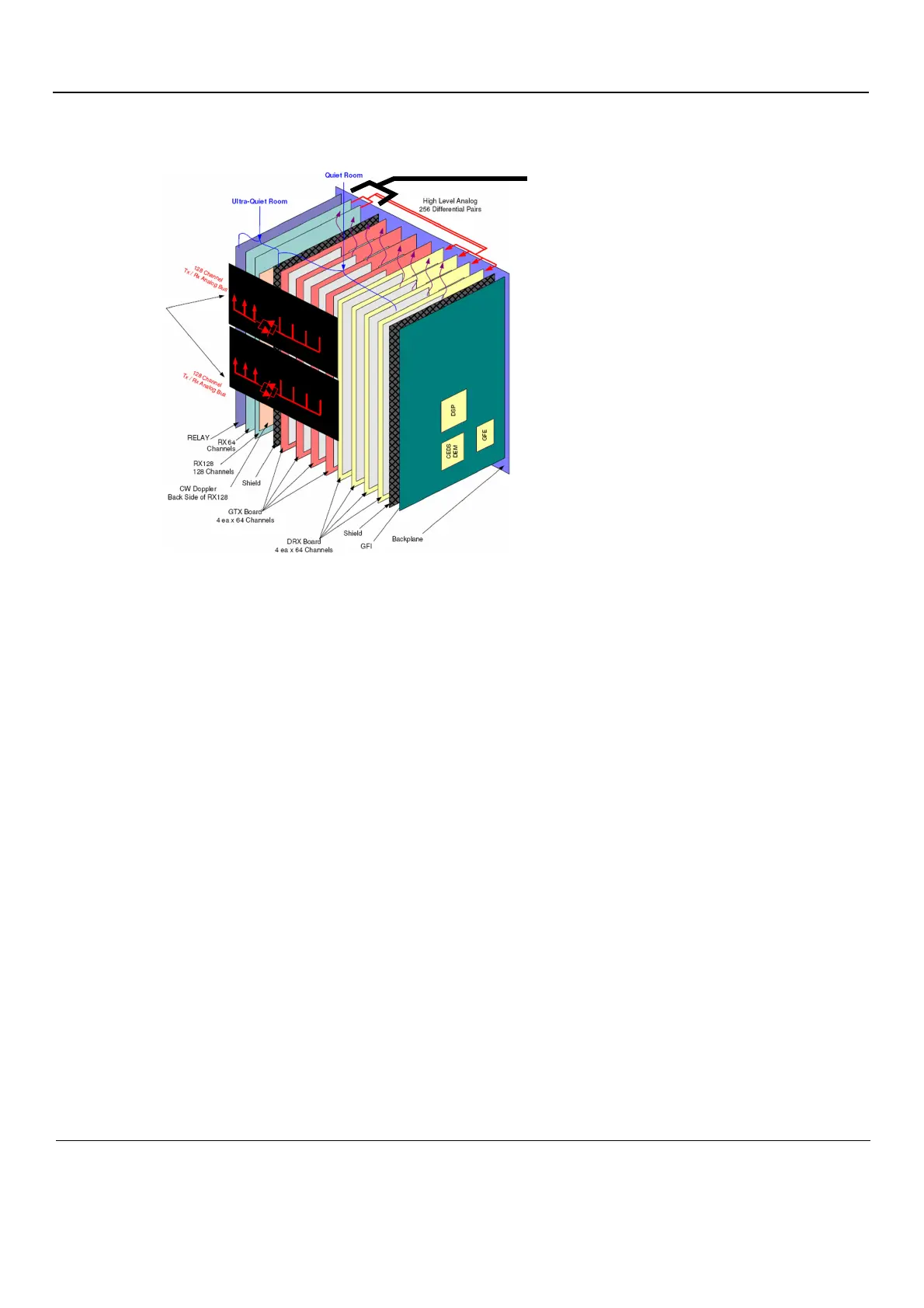
5 - 42 Section 5-8 - Front End Processor (FEP)
5-8-5-2 Location in the Unit
5-8-5-3 Input DC Voltages
•+6 VDC
•-5 VDC
• +15 VDC
• -15 VDC
5-8-5-4 Outputs
• After Time Variable Amplification the analog signals are sent via high level, analog, differential lines
to the DRX board for A/D conversion and beamforming.
• When using the Pedof probe, the demodulated Doppler signals are sent to the DRX board for A/D
conversion.
5-8-5-5 LEDs on the GRX board
The GRX board has four LEDs:
Figure 5-28 GRX location
2 pc GRX boards