GE H
EALTHCARE
D
IRECTION
GA091568, R
EVISION
5 VIVID E9 S
ERVICE
M
ANUAL
Chapter 8 - Replacement procedures 8 - 143
8-6-22-6 Install the USB Video Board Flex Cable
1.) Connect the USB Video Board Flex Cable to the USB Video Board and the other end to the LCD
(Touch) Display.
2.) Install the Rear Cover on the Operator Panel, Upper.
3.) Install the Operator Panel, Upper.
4.) If removed, install the Operator Panel, Lower.
8-6-22-7 Disconnect the HV Inverter Cable
The HV Inverter Cable is the cable between the HV Inverter board and the Main Controller board.
1.) Remove the Rear Cover on the Operator Panel, Upper.
2.) Disconnect both ends of the cable and remove it.
8-6-22-8 Install the HV Inverter Cable
1.) Connect the HV Inverter Cable to the HV Inverter board and the other end to the Main Controller
board.
2.) Install the Rear Cover on the Operator Panel, Upper.
3.) Install the Operator Panel, Upper.
4.) If removed, install the Operator Panel, Lower.
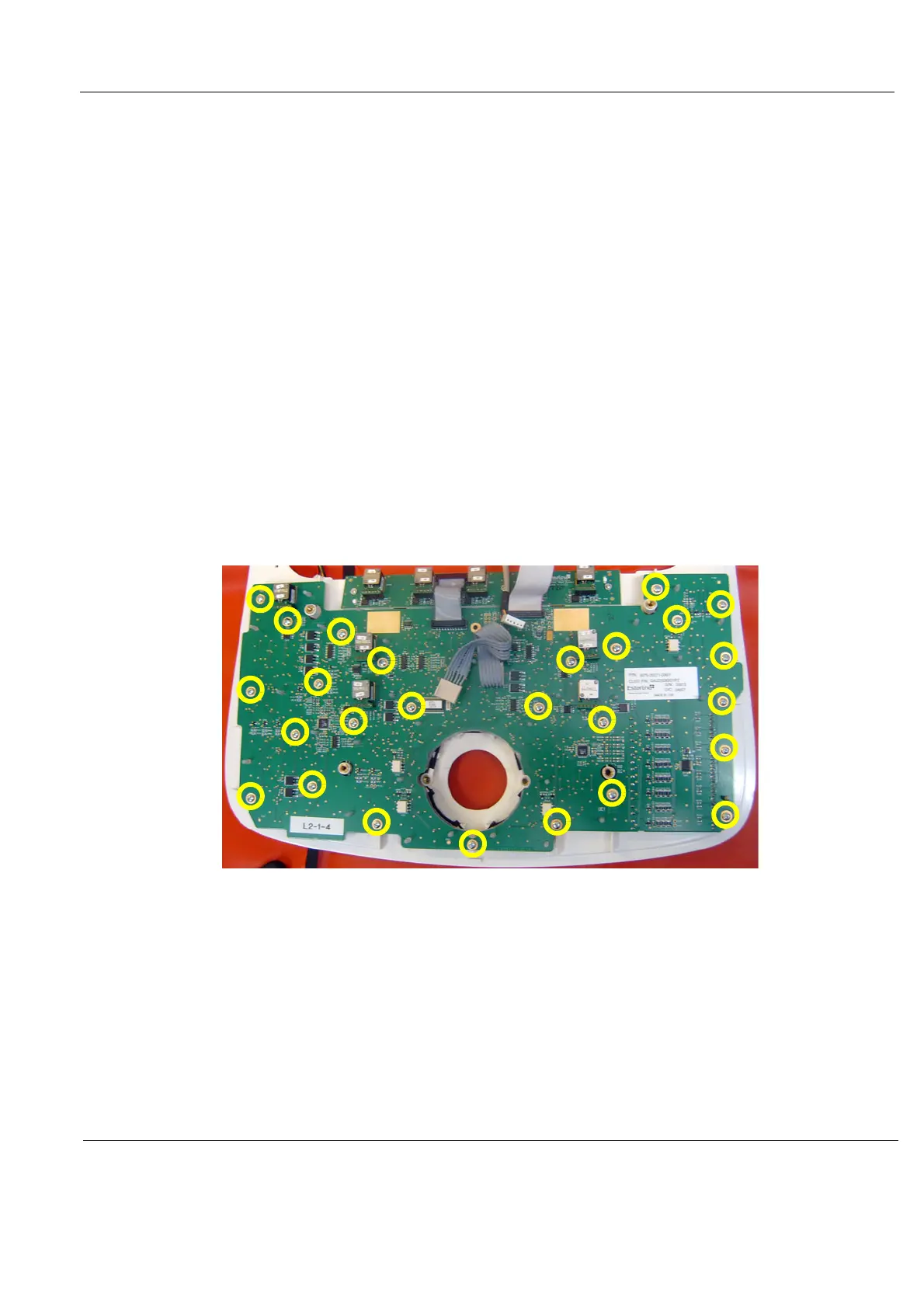
Figure 8-154 Lower Switch Board with Elastomer - Trackball already removed