GE H
EALTHCARE
D
IRECTION
GA091568, R
EVISION
5 VIVID E9 S
ERVICE
M
ANUAL
8 - 186 Section 8-7 - Replacing XYZ Parts
8-7-5-2 Drive Gear Assembly removal procedure
The Drive Gear Assembly is a part of the Z Mechanism. To remove the Drive Gear Assembly, follow
these steps:
1.) Disconnect the motor cable from the XYZ Control Box.
2.) Unscrew and remove the four fixing screws.
3.) Pull the unit away. You may need to either operate the Z-release lever when pulling, or move the
Top Console slightly up or down to make the wheel disengage from the gear.
8-7-5-3 Drive Gear Assembly installation procedure
1.) Position the Drive Gear Assembly in the correct position. You may need to either operate the Z-
release lever when positioning, or move the Top Console slightly up or down to engage the teeth
on the wheel with the teeth on the gear.
2.) Install the four (4x) fixing screws with washers. (M6 x 16, Torque: 9,5 Nm.)
Figure 8-194 Drive Gear Assembly location
Figure 8-195 Remove four screws
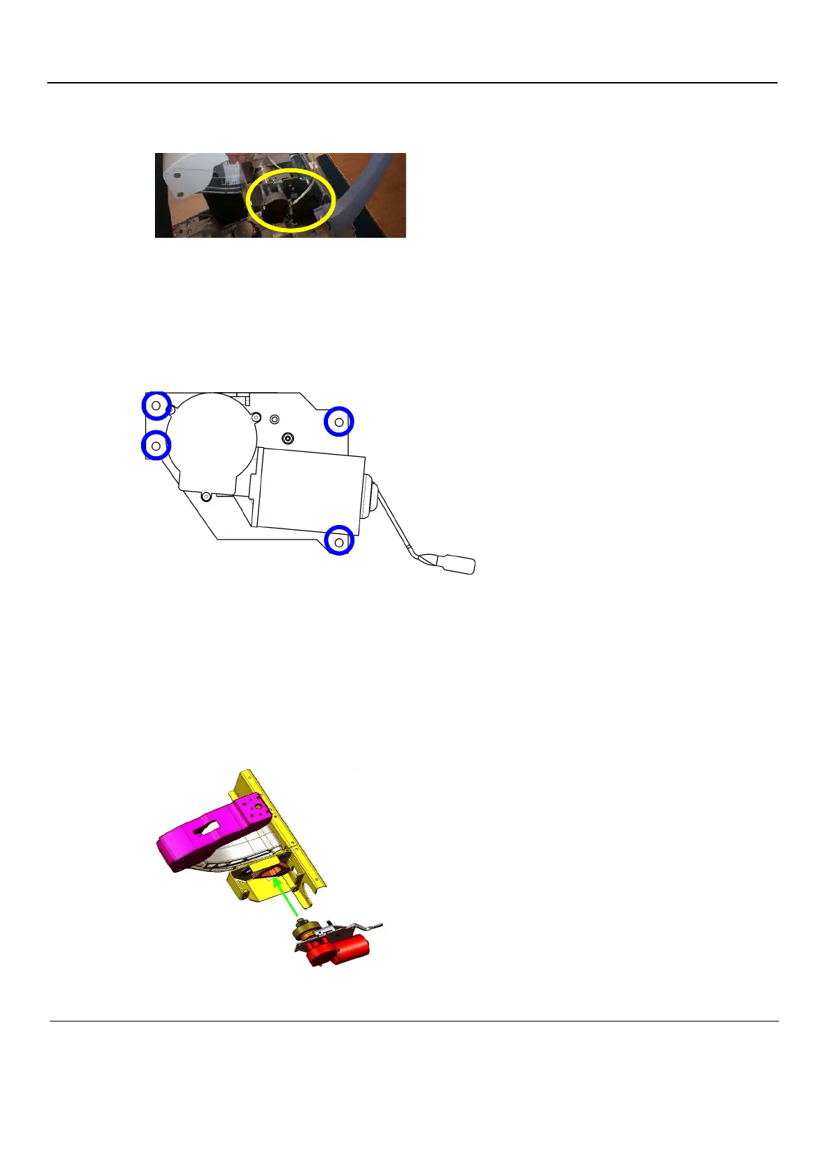
Figure 8-196 Install the Drive Gear Assembly