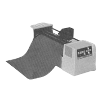
8 Chapter 1, Installation
The numbers in the diagram match the parts described below.
1.
Control Panel
: Indicator LEDs and control keys.
2.
Power Switch
: Turns the cutter on or off.
3.
Carriage Cover
: For safety reasons, the cutter will not work with the
cover open. The cover also prevents objects from falling into the
cutting zone.
4.
Roll Support System
: Carries the conveyor rolls.
5.
Conveyor Rolls
: Hold roll material.
6.
Guiding Flanges
: Located on the conveyor rolls, prevent the roll of
material from shifting to the left or right when material is pulled from the
roll.
7.
Material Hold Lever
: Raises and lowers the pressure rollers. Lowering
the pressure rollers holds the material in place.
8.
Platen and Drive Roller Cover
: Supports the cutting material and
guides the movement of the material along the X-axis.
9.
Cutting Mat
: Provides a reliable cutting surface and prevents damage
to the knife tip.
10.
Serial Interface Connector
: RS-232C serial interface connector to
connect the cutter to the host computer.
11.
Parallel Interface Connector
: Centronics parallel connector to
connect the cutter to the host computer's printer port for fast data
transfer.
12.
Power Connector
: Connector for the power cord, which plugs into the
main power supply of the cutter.
13.
Tool head with Tool Mounting Bracket
: All available tools such as
knife holders, drawing pens, and painting pens can be secured into the
tool head using the locking screw. The tool head moves along the Y-
axis to the exact cutting position.
14.
Drive Rollers
: Move the cutting material along the X-axis.
15.
Pressure Rollers
: Hold the material against the drive rollers during
cutting.