GDS3710 User Manual
Version 1.0.7.8
Alarm IN/OUT
Alarm_In could use any 3rd party Sensors (like IR Motion Sensor).
Alarm_Out device could use 3rd party Siren and Strobe Light, or Electric Door Striker, etc.
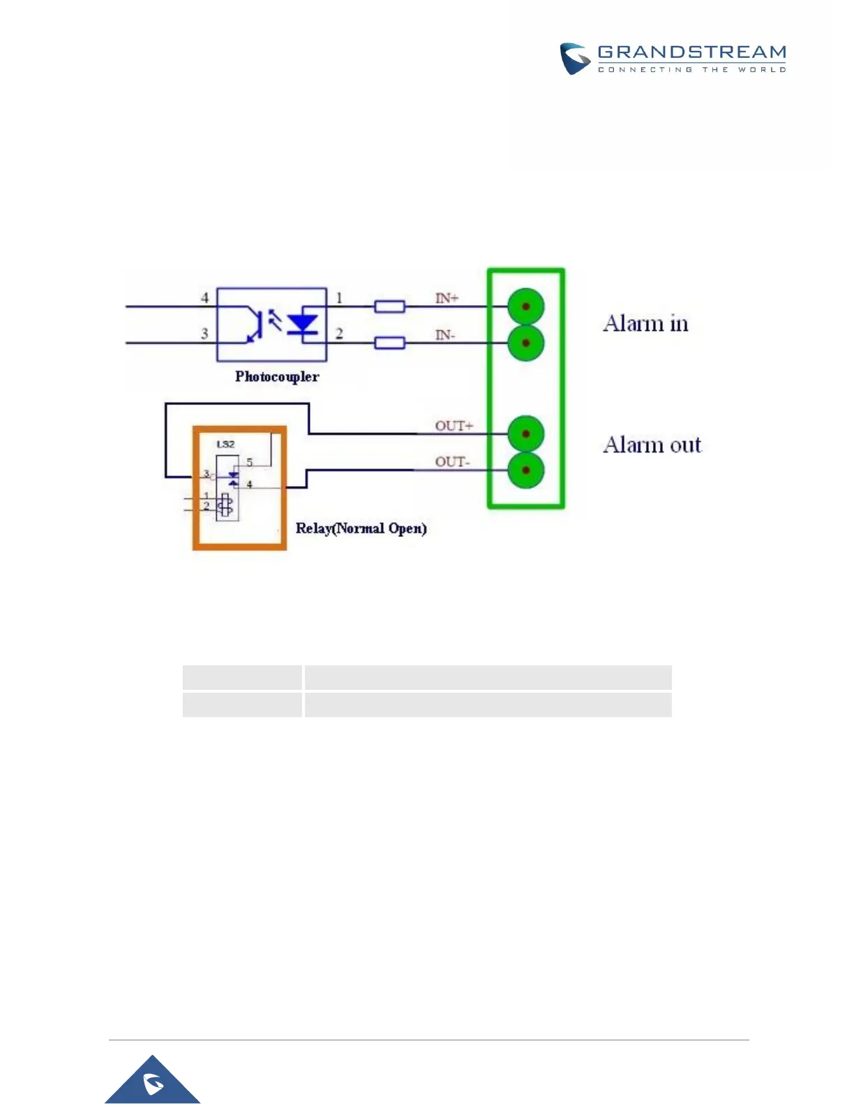
The figure below shows illustration of the Circuit for Alarm_In and Alarm_Out.
Figure 18: Alarm_In/Out Circuit for GDS3710
Notes:
• The Alarm_In and Alarm_Out circuit for the GDS3710 should meet the following requirement:
3V<Vin<15V, PINs (1.02KΩ)
125VAC/0.5A, 30VDC/2A, Normal Open, PINs
• The Alarm_In circuit, if there is any voltage change between 3V and 15V, as specified in the table
above, the GDS3710 Alarm_In port will detect it and trigger the action and event.
• Higher voltage and wrong polarity connection are prohibited because this will damage the devices.
Protection Diode
When connecting the GDS3710 to a door strike it is recommended to set an EMF protection diode in reverse
polarity for a secure use, below examples of deployment for the protection diode.
 Loading...