FC4200-UM-251-03-9370 16
REPLACEMENT PROCEDURES
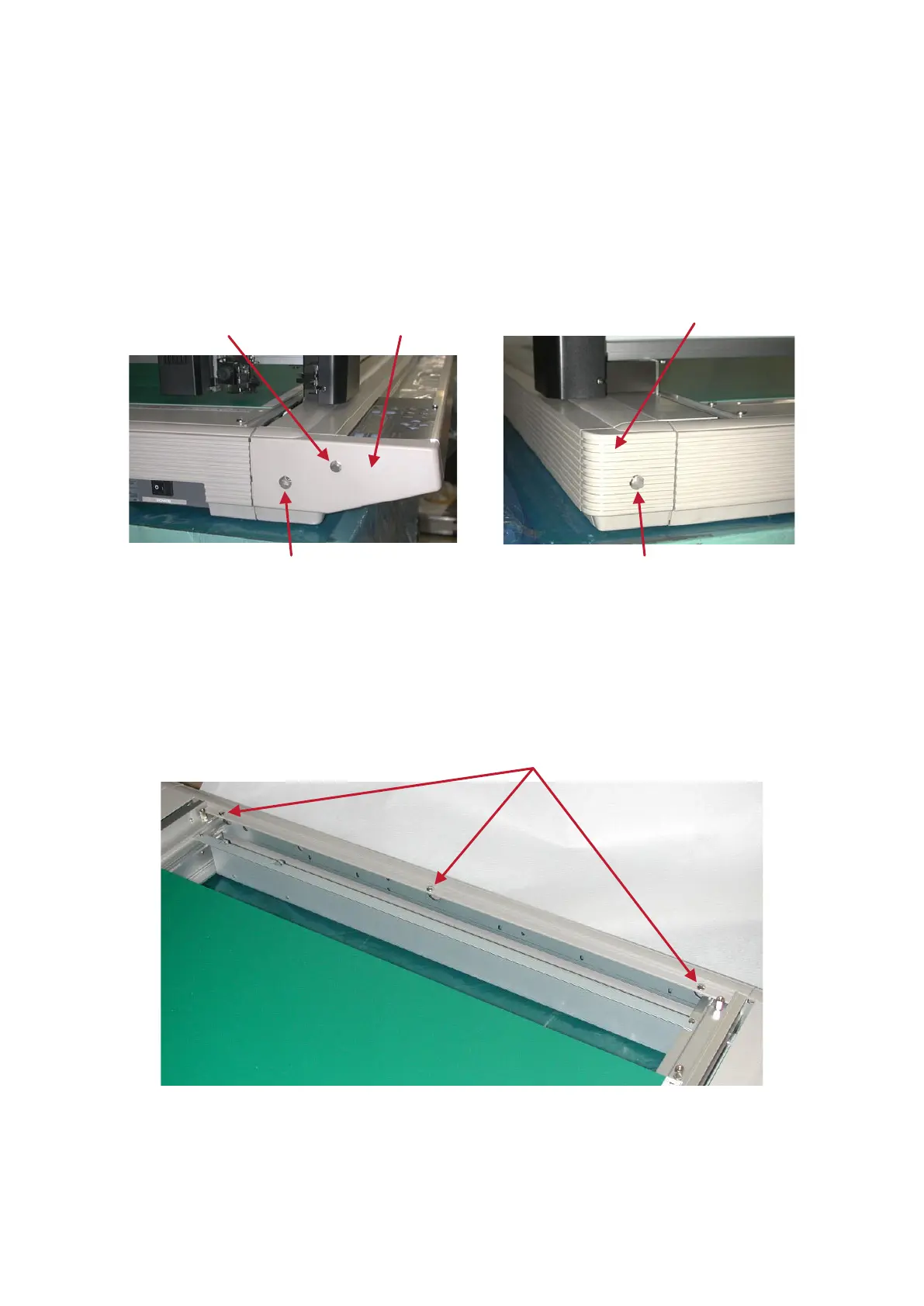
6.4 Removing the Corner Cover
Remove the two screws securing the Corner Cover 50L (left side) and Corner Cover 50R (right side) at
the corners on the operation side (M3L10 tapping screw and M4L8 binding head screw, one pc. each),
followed by the Corner Cover 50L and Corner Cover 50R.
Remove the M4L8 binding head screws securing the Corner Cover A (on right back side) and Corner
Cover B (on left back side) on the main unitʼs rear side, followed by Corner Covers A and B.
To replace the Corner Cover, reverse the above procedure.
Corner Cover B
Corner Cover 50L
M4L8 binding head screw
M3L10 tapping screw
M4L8 binding head screw
6.5 Removing the Right Side Cover
Remove the four M4L8 binding head screws securing Panel R, and then Panel R.
Remove Corner Cover A (on the right back side) and Corner Cover 50R.
Remove the seven screws securing the Side Cover (three screws at the top and four TP screws at the
bottom), followed by the Side Cover.
To replace the Right Side Cover, reverse the above procedure.