FC4200-UM-251-03-9370 17
REPLACEMENT PROCEDURES
6.6 Removing the Interface Cover
Remove the four M4L6 binding head screws securing Panel L, followed by Panel L.
Remove Corner Cover A (on the right back side) and Corner Covers 50R and 50L.
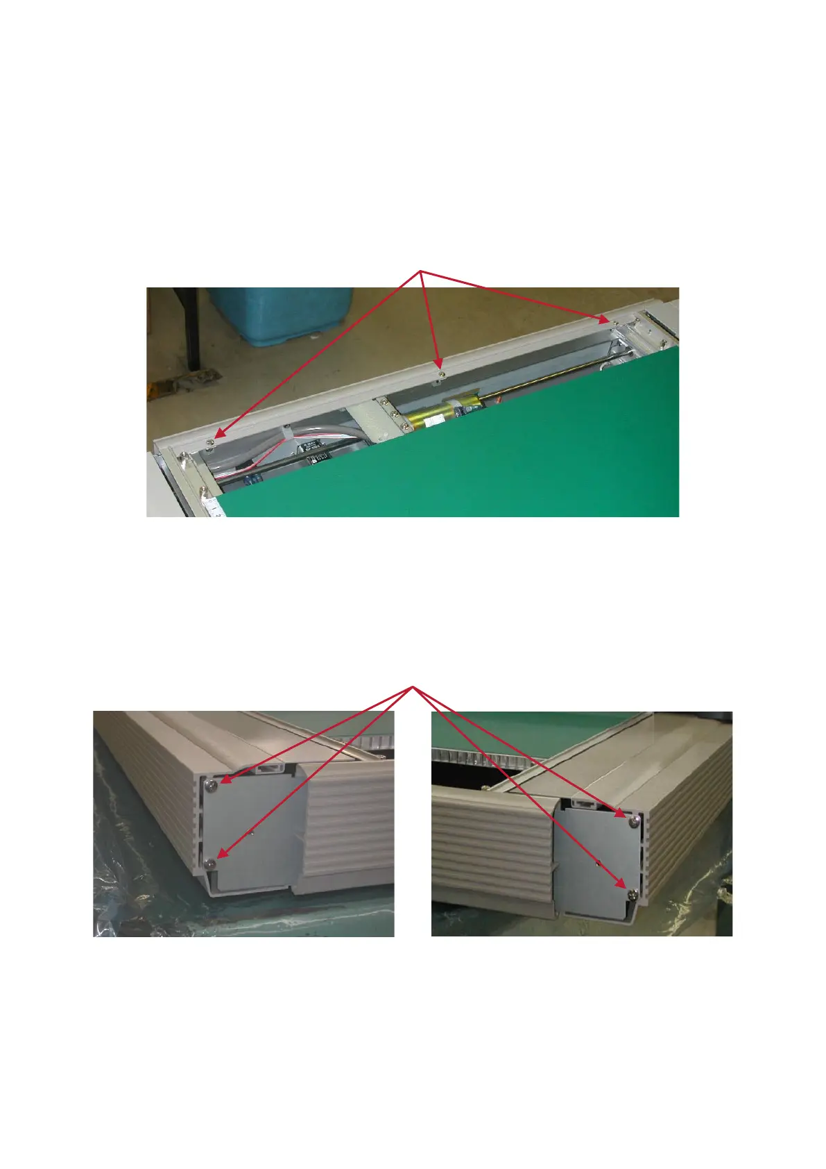
Remove the five screws securing the Interface Cover (three screws at the top and two TP screws at the
bottom), followed by the Interface Cover.
To replace the Interface Cover, reverse the above procedure.
6.7 Removing the Rear Cover
Remove Corner Cover A (on the right back side) and Corner Cover B (on the left back side).
Remove the seven screws securing the Rear Cover (2 x 2 screws on the corner cover side and three TP
screws at the bottom), followed by the Rear Cover.
To replace the Rear Cover, reverse the above procedure.