FC4200-UM-251-03-9370 46
ELECTRICAL SECTION
7.11 Verifying the Carriage Check Position (FC4200-50 / 60 only)
1. Set the DIP switch to adjustment mode and switch on power.
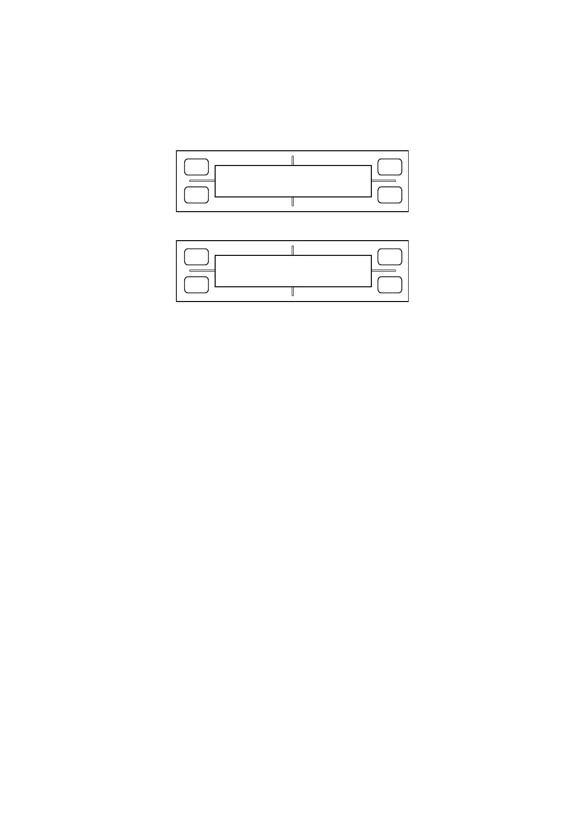
2. Hold down the [Next Page] key until the LCD displays the following:
FORCE
SPEED
OFFSET
QUALITY
F1 F3
F4
F2
SET CARCHK POS
PRESS ENTER KEY!!
3. Press the [Enter] key. The LCD display changes to display the following:
FORCE
SPEED
OFFSET
QUALITY
F1 F3
F4
F2
X= 0 1ST Y=+230
X=- 70 1ND Y=+230
The values shown here indicate the position to which the plotter moves as it performs carriage pen check
operations. This is a two-step operation; after retracting to the “1st” position, the plotter performs a pen-
down operation at the “2nd” position.
4. Press the [TEST] key to prompt the plotter to perform a carriage pen check operation. Check that the No.
1 and No. 2 pens both are placed almost at center of the rubber plate.
If the pens are not at the center of the rubber plate, their positions can be adjusted as described below.
(1) Select the item you want to modify, using keys [F1] through [F4].
(2) Modify the value using the position keys [Up] or [Down]. The value here indicates a coordinate position
in increments of 0.1 mm.
(3) Press the [Enter] key to confirm the value youʼve set.
5. Press the [Next Page] key to finish.