FC4200-UM-251-03-9370 39
ELECTRICAL SECTION
7.5 Adjusting the Mark Sensor Level
Correctly connect the connectors for all wire materials before performing the operation described below.
1. Set the DIP switch to adjustment mode (or normal mode).
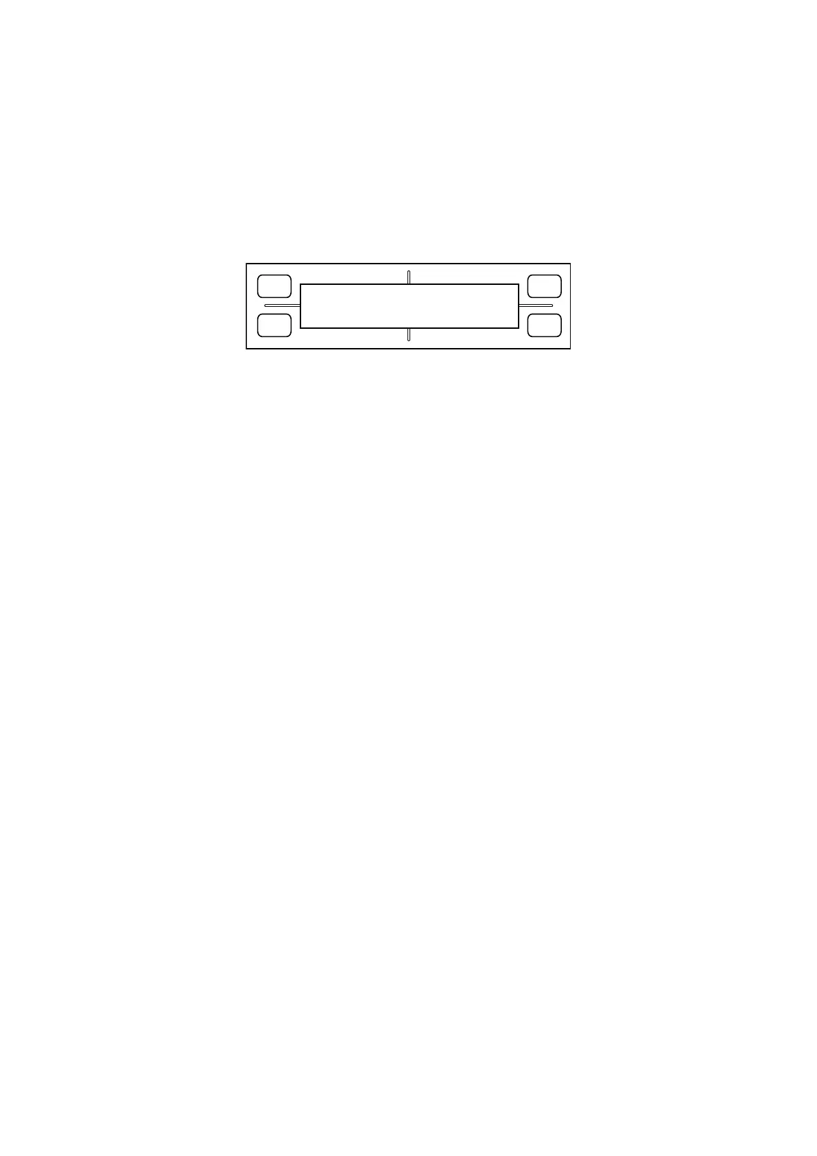
2. Hold down the POSITION keys “Left” and “Right” while switching on power. The LCD displays the follow
-
ing:
FORCE
SPEED
OFFSET
QUALITY
F1 F3
F4
F2
0 0% MAX
3. Place white paper for adjustment use on the panel, making sure that no part of it is raised above the sur-
face. Move the mark sensor by hand to the position exactly above the paper. The bar graph shown in the
lower row of the LCD will indicate, as a percentage value, the amount detected of reflected sensor light.
On the main board, turn VR1 clockwise or counterclockwise to adjust the indicated value in the range 27–
30%.
4. Switch off power.