6 – 3
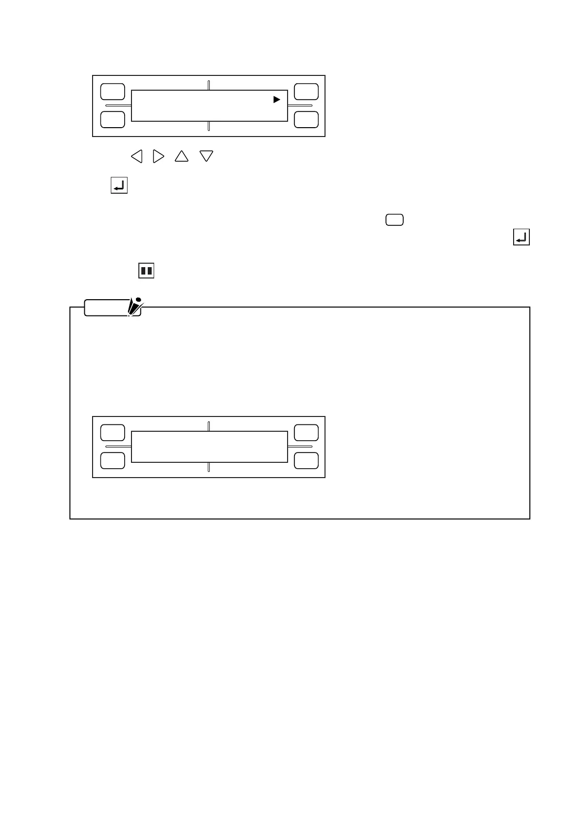
(6) After you finish specifying the L.L. point, the following menu appears for specifying the U.R. point.
Use the , , , POSITION keys to move the pen carriage to the upper right corner of the
desired area with respect to the current origin position. When you are satisfied with the position, press
the ENTER key to register your U.R. setting. At such time, the coordinate values shown repre-
sent the distance from the current origin position to the current position of the pen carriage.
If the current U.R. position does not need to be changed, press the
F3
(DEFAULT) key to make the
pen carriage’s current position the default U.R. point. In this case, you need not press the
ENTER key.
(7) Press the PAUSE key to return the plotter to READY status.
NOTE
• After the AREA settings have been specified, the pen carriage will move to the specified lower left
point.
• The AREA function is used to set both the L.L. (Lower Left) and U.R. (Upper Right) points. When
you incorrectly specify these points (by, for example, failing to allow at least 5 mm along the X and
Y axes between the upper left and lower right points or between the lower left and upper right
points), the message below is displayed for several seconds. If this happens, re-specify your
AREA settings correctly.
• Your AREA settings will be reset to their default values (the plotter’s maximum cutting/plotting
area) whenever the ROTATE or MIRROR setting is switched ON or OFF.
FORCE
SPEED
OFFSET
QUALITY
F1 F3
F4
F2
SET U.R. DEFAULT
X= 0 Y= 0
FORCE
SPEED
OFFSET
QUALITY
F1 F3
F4
F2
ILLEGAL PLOT AREA