- 78 -
CROSS SECTION OF THE CABLES
The manufacturer recommends that the INPUT/OUTPUT and BATTERY cables pass under the CPS unit.
Please refer to the following table for the minimum cross-sections to be used for the input and output cables.
INPUT
mains /
separate bypass (optional)
*
The cross-sections indicated in the table refer to a maximum cable length of 10 metres.
**
The maximum length of the cables for connection to the optional Battery Box is 3 metres.
Note: the maximum cable size that can be inserted in the INPUT, BYPASS and OUTPUT terminal boards is 25mm
2
for
cables with cable lugs and 35mm
2
for rigid cables.
The maximum section for cables that can be inserted in the BATT terminal board is 10 mm
2
for cables with cable lugs
and 16 mm
2
for stripped cables.
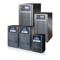
CONNECTIONS
The very first connection must be the protection conductor or the earth cable which should be
inserted in the terminal marked PE. The CPS must be earthed before use.
Connect the input and output cables to the terminal board as shown in the figure below:
THE INPUT AND BYPASS NEUTRAL MUST ALWAYS BE CONNECTED.
THE INPUT AND BYPASS LINES MUST REFER TO THE SAME NEUTRAL POTENTIAL.
Note: connections to the BATTERY module are only required when the optional Battery Box is present.