APS-7000 Series User Manual
150
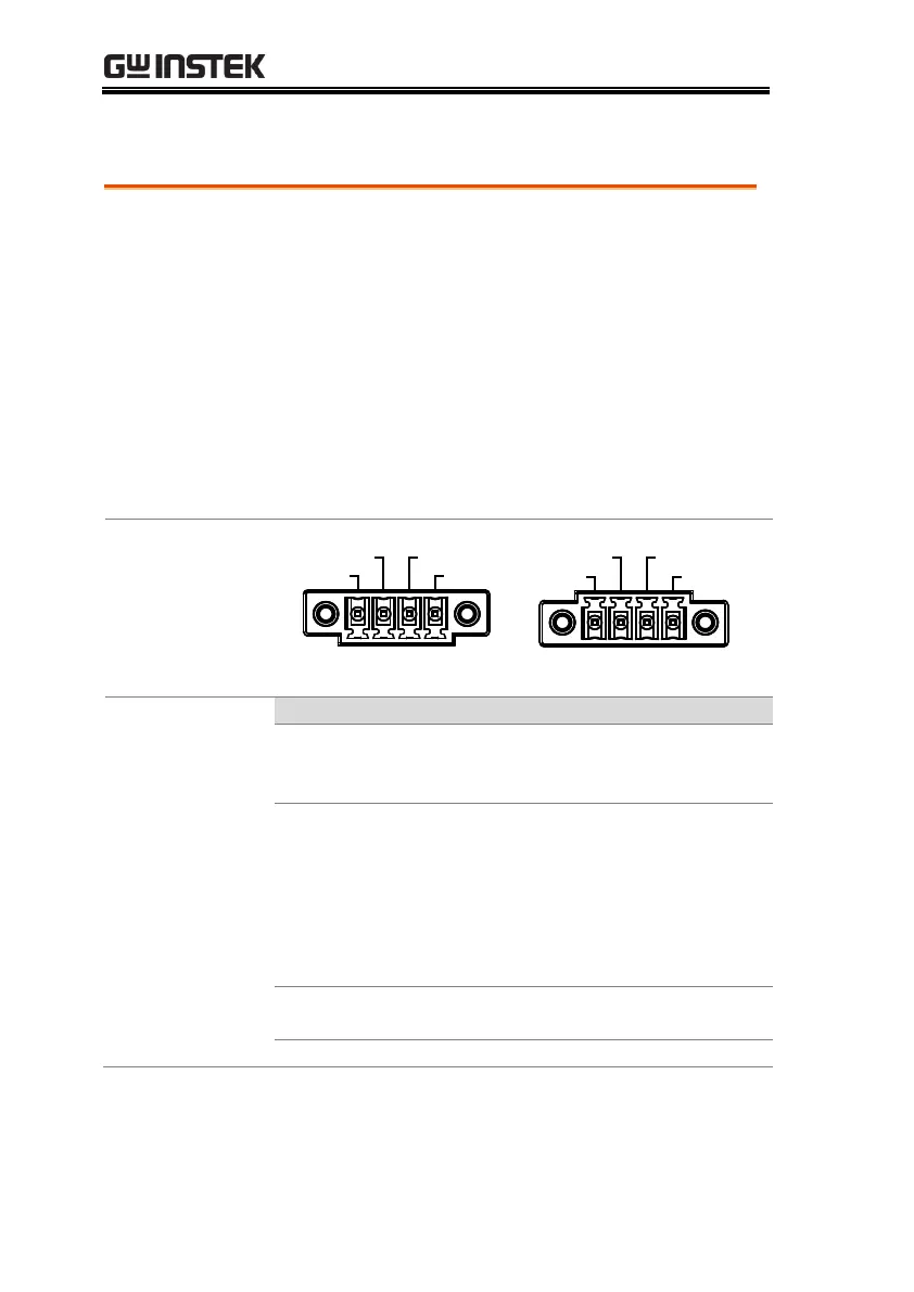
J1 Connector Overview
The J1 connector is primarily used for
triggering and for monitoring the status of the
power supply. Each pin is isolated from the
power supply (photo coupled). The Trigger In
and Out On/Off input can accept up to
30V/8mA. The Trigger Out port is pulled high
internally to +5V.
The trigger control menu configures the Trigger
In and Trigger Out pins. See page 93 for details
on the trigger control settings.
Trigger Out
Trigger In Out On / Off
COM
APS-7050 and APS-7100
Trigger Out
Trigger In
Out On / Off
COM
APS-7200 and APS-7300
Outputs a high signal (+5V) according
to the Trigger Out settings in the
Trigger Control menu.
Applying a high level signal to the
Trigger In pin performs an action
according to the settings in the Trigger
Control menu. Actions include,
turning the output on, loading a
setting or loading one of the preset
settings.
Applying a high level signal to this
port will turn the output on by default.
 Loading...