1-4
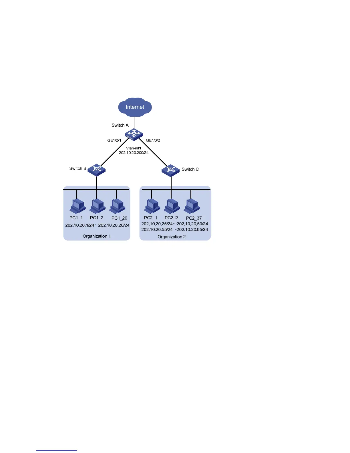
z Allow the PCs of Organization 2 to access the external network through GigabitEthernet 1/0/2 of
Switch A.
z GigabitEthernet 1/0/1 and GigabitEthernet 1/0/2 belong to VLAN 1. The IP address of
VLAN-interface 1 is 202.10.20.200/24.
z PCs of Organization 1 are isolated from those of Organization 2 on Layer 2.
Network diagram
Figure 1-3 Network diagram for combining access management and port isolation
Configuration procedure
Perform the following configuration on Switch A.
For information about port isolation and the corresponding configuration, refer to the Port Isolation
Operation.
# Enable access management.
<Sysname> system-view
[Sysname] am enable
# Set the IP address of VLAN-interface 1 to 202.10.20.200/24.
[Sysname] interface Vlan-interface 1
[Sysname-Vlan-interface1] ip address 202.10.20.200 24
[Sysname-Vlan-interface1] quit
# Configure the access management IP address pool on GigabitEthernet 1/0/1.
[Sysname] interface GigabitEthernet 1/0/1
[Sysname-GigabitEthernet1/0/1] am ip-pool 202.10.20.1 20
# Add GigabitEthernet 1/0/1 to the port isolation group.
[Sysname-GigabitEthernet1/0/1] port isolate
[Sysname-GigabitEthernet1/0/1] quit
 Loading...


