325
Port-based multicast VLAN configuration example
Network requirements
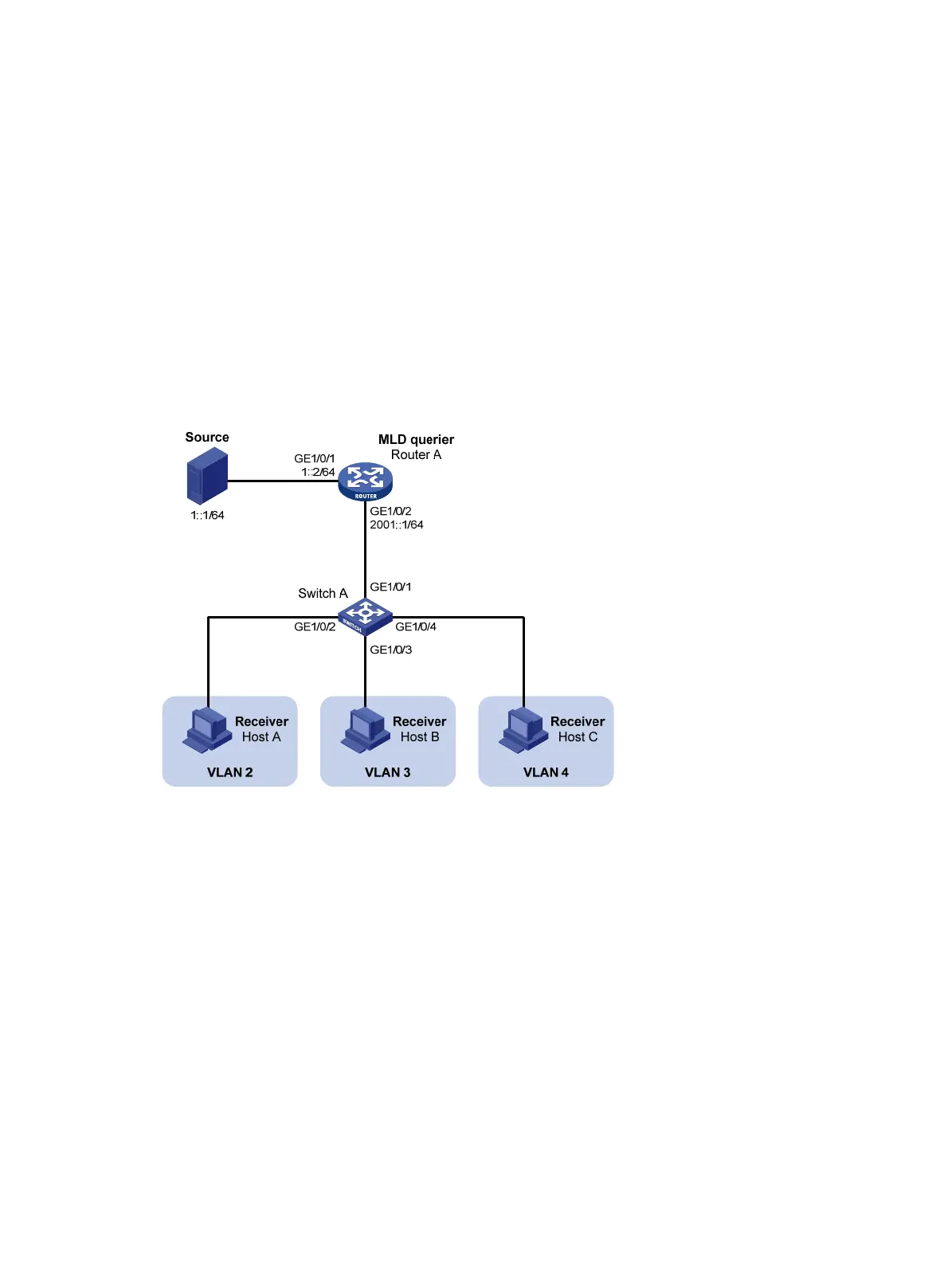
As shown in Figure 81, MLDv1 runs on Router A. MLDv1 snooping runs on Switch A. Router A acts as the
MLD querier. The IPv6 multicast source sends IPv6 multicast data to IPv6 multicast group FF1E::101. Host
A, Host B, and Host C are receivers of the IPv6 multicast group. The hosts belong to VLAN 2 through
VLAN 4 respectively.
Configure the port-based IPv6 multicast VLAN feature on Switch A so that Router A sends IPv6 multicast
data to Switch A through the IPv6 multicast VLAN, and Switch A forwards the IPv6 multicast data to the
receivers that belong to different user VLANs.
Figure 81 Network diagram
Configuration procedure
1. Enable IPv6 forwarding on each device, and configure the IPv6 address and address prefix for
each interface as per Figure 81. (Details
not shown.)
2. On Router A, enable IPv6 multicast routing, enable IPv6 PIM-DM on each interface, and enable
MLD on the host-side interface GigabitEthernet 1/0/2.
<RouterA> system-view
[RouterA] multicast ipv6 routing-enable
[RouterA] interface gigabitethernet 1/0/1
[RouterA-GigabitEthernet1/0/1] ipv6 pim dm
[RouterA-GigabitEthernet1/0/1] quit
[RouterA] interface gigabitethernet 1/0/2
[RouterA-GigabitEthernet1/0/2] ipv6 pim dm
[RouterA-GigabitEthernet1/0/2] mld enable
3. Configure Switch A:

 Loading...


