422
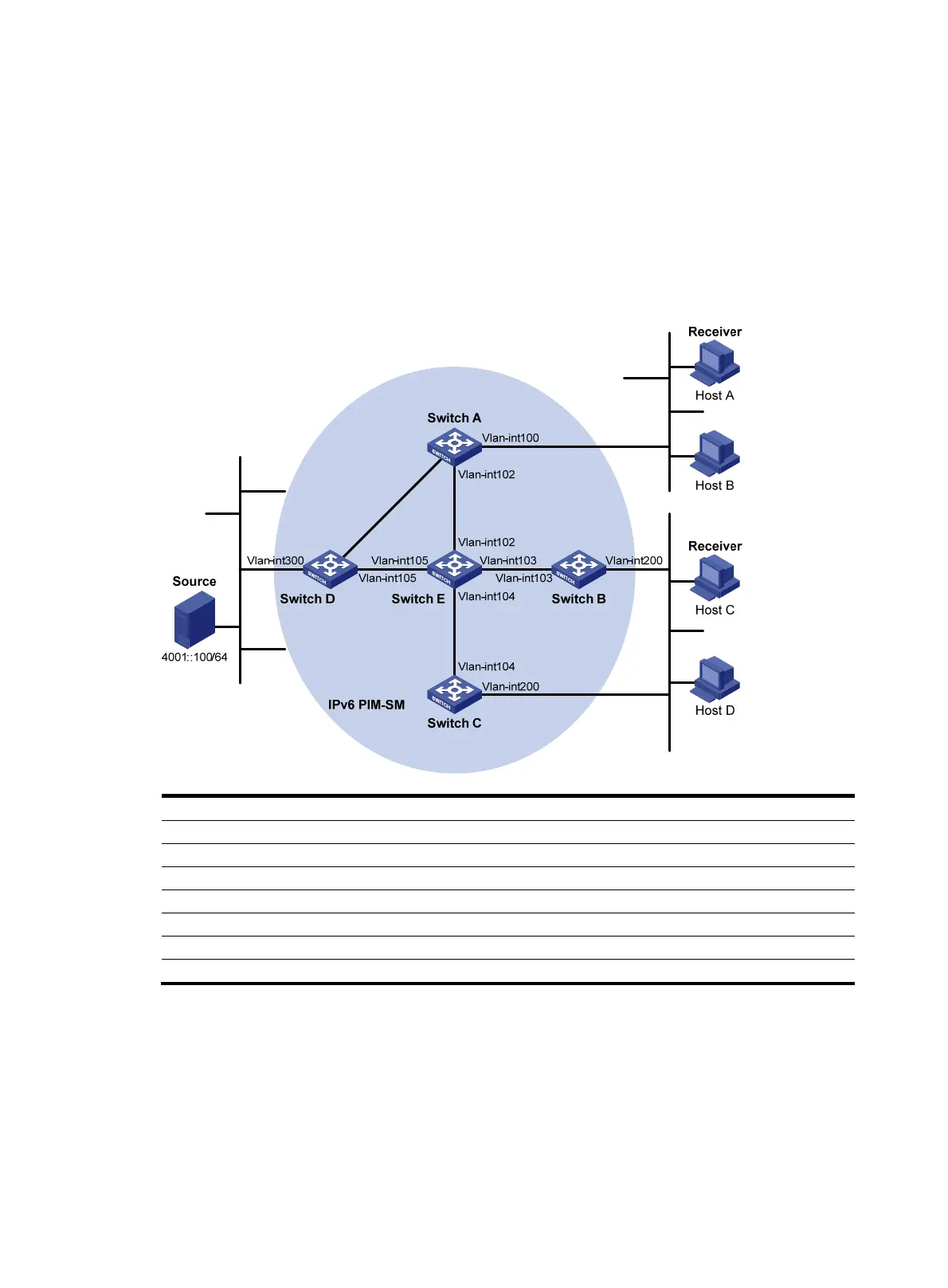
Host A and Host C are IPv6 multicast receivers in two stub networks, N1 and N2.
VLAN-interface 105 on Switch D and VLAN-interface 102 on Switch E act as C-BSRs and C-RPs. The
C-BSR on Switch E has a higher priority. The IPv6 multicast group range to which the C-RP is designated
is FF0E::101/64. Modify the hash mask length to map a certain number of consecutive IPv6 group
addresses within the range to the two C-RPs.
MLDv1 runs between Switch A and N1 and between Switch B/Switch C and N2.
Figure 106 Network diagram
Device Interface IPv6 address
Device
Interface IPv6 address
Switch A Vlan-int100 1001::1/64 Switch D Vlan-int300 4001::1/64
Vlan-int101 1002::1/64
Vlan-int101 1002::2/64
Vlan-int102 1003::1/64
Vlan-int105 4002::1/64
Switch B Vlan-int200 2001::1/64 Switch E Vlan-int104 3001::2/64
Vlan-int103 2002::1/64
Vlan-int103 2002::2/64
Switch C Vlan-int200 2001::2
64
Vlan-int102 1003::2/64
Vlan-int104 3001::1/64 Vlan-int105 4002::2/64
Configuration procedure
1. Enable IPv6 forwarding on each switch and configure the IPv6 address and prefix length for each
interface as per Figure 106. (Details not shown.)
2. Configure OSPFv3 on the switches in the IPv6 PIM-SM domain to make sure the switches are
interoperable at the network layer. (Details not shown.)
3. Enable IPv6 multicast routing, MLD and IPv6 PIM-SM
Ethernet
EthernetEthernet
N1N2
Vlan-
i
nt1
01
Vlan-int10
1

 Loading...


